You are using an out of date browser. It may not display this or other websites correctly.
You should upgrade or use an alternative browser.
You should upgrade or use an alternative browser.
Cheap smps base on TL494 pwm, half bridge AC-DC
- Thread starter norazmi
- Start date
sorry my previous post its not EI33, its EE16 for the aux supply originally from atx supply. Yes u can use PC817 opto without problem, all u need is watch the pin configuration. I already put all thing at 1st page, for the aux supply if u want to use flyback module u need to refer to the atx original circuit and you need to make some modification from original circuit to put new aux supply with flyback by using EE16. EE19 actually bias trafo. U can use EI or EE core is your choice no problem with that.
I think better we discuss here so anybody can share the ideas
I think better we discuss here so anybody can share the ideas
padmanabhan
New member
Hi Norazmi,
i would like to build this SMPS, but what would be the max wattage it can handle, and the designed output voltage. driver trans details please.
regards
padmanabhan
i would like to build this SMPS, but what would be the max wattage it can handle, and the designed output voltage. driver trans details please.
regards
padmanabhan
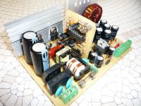
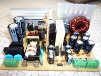
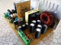
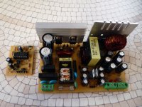
i`ll put some photo here, voltage is stable so far with max load arround 300-350 watts at nominal p-out. The hi voltgate bipolar easy get hot when u trying to push hard and u need proper fan to cooler the power transistor. But with proper winding trafo and proper heatsink for the power transistor like MJE13009 or maybe more higher u can obtain about 400-450 watts.
As u can see the this smps have feedback with opto coupler and using trimpot and u can have variable output voltage base on your winding section which has been explain before at first page. The output voltage is depends on your winding primary and secondary and its variable, using different size of trafo also may effect the output voltage. so u need to have calculate by urself base on my basic calculation at first page or u can use Deminis software provide to calculate it.
Vorez, i dont have time yet to re-draw new schema with flyback circuit but i`ll try to put here example from original schema from atx supply which u can refer to it to build aux supply, or easy way u can use external aux supply with linear transformer. Ill put some photo here for reference.
regards.
padmanabhan
New member
Hi Norazmi,
thanks for the kind reply, but pl do share the Trafo details.
Thanks and regards
padmanabhan
thanks for the kind reply, but pl do share the Trafo details.
Thanks and regards
padmanabhan
Hi mike ,
There is no mistake, the different just my typo for the Tertiary, so i write it as secondary +/- 15v as it should be write as Tertiary. Secondary still 11 + 11 laps means 22 laps in total.
Hi Norazmi,
Is the secondary and tertiary winding are both center top?
Yes mike, the GND must be tight together.
Thanks, I'm just confused in the snubber placement for both secondary and tertiary. For the secondary it was in "q" and "r " and "s" and "r". for the the tertiary it was placed in "t" and "u". I'll be just making a single rail center top, so I don't have any negative voltage. I'm just confused in the placement of the secondary snubber for a singlerail center top, is it in point "q" and "s" or is it just in "q" and "r" alone?
hope you can help me on this.
thanks.
vorez yes i can surely understand u , hmm i dont have facebook lol, really because i dont have time to play with it. But still u can ask me here so we can share the ideas together with others too.
Mike do not worry i`ll try to explain to u, secondary will be "q to r" "r to s" where "r" is the center (GND) and there is 2 snubber, 1 is for secondary and another is for tertiary. 1 snubber will be at "q to s" and another will be "t to u". Winding instruction for the tertiary will be "t to r" and "r to s" where r is the center (gnd) together with secondary GND. They will be tight together and have same GND placement.
So i hope i can clear ur confusion here. Because tertiary will be dual rail which can provide +/-12 or +/-15 its up to u to use either 7812&7912 or 7815&7915.
regards
Azmi
, hmm i dont have facebook lol, really because i dont have time to play with it. But still u can ask me here so we can share the ideas together with others too.Mike do not worry i`ll try to explain to u, secondary will be "q to r" "r to s" where "r" is the center (GND) and there is 2 snubber, 1 is for secondary and another is for tertiary. 1 snubber will be at "q to s" and another will be "t to u". Winding instruction for the tertiary will be "t to r" and "r to s" where r is the center (gnd) together with secondary GND. They will be tight together and have same GND placement.
So i hope i can clear ur confusion here. Because tertiary will be dual rail which can provide +/-12 or +/-15 its up to u to use either 7812&7912 or 7815&7915.
regards
Azmi
HI Azmi, i compared schema, pcblayout and GDT EE16 from PC PSU, i see that pin configuration not match with PCB lay out. some pin must be jumper to proper track. or i am wrong? would you pls post picture of bottom track of your PCB. I need to clarify this before make a try. thank you
Regards
Glo
Regards
Glo
Yes, it is as long as u know which correct connection between them, because some old psu come with different leg combination, so we must watch it. This is the reason this cheap smps become complicated with driver transformer for the first try, we need to understand correctly where to connect them. i also do jumper for driver transformer and some i just place it where there is correct one. its depend how the driver trafo we can get. This one is more cheaper than ir2153 but little complicated for driver transformer, thats the key, when u understand how its work, there it would be more easy for the next time setup and build.