First smps

brady

Member
Hello,

I am a third year Electrical Engineering student. I am interested in designing and building my first smps and figured this would be the best place to get a start. I have studied smps topologies for some time now but lack some knowledge in computations.

Here are some design parameters that I am looking to achieve:

Input: 120V nominal @ 60 Hz (No voltage doubler needed)
Output: 2 X 32V @ 150W each.

I was considering a push-pull topology, but I do not fully understand how to design the current-mode feedback loops.

Any help is appreciated. If this project would be too complex for a first project then I am open to considering a different topology for my first design experience.

- Brady
 

Silvio

Well-known member
Hello,

I am a third year Electrical Engineering student. I am interested in designing and building my first smps and figured this would be the best place to get a start. I have studied smps topologies for some time now but lack some knowledge in computations.

Here are some design parameters that I am looking to achieve:

Input: 120V nominal @ 60 Hz (No voltage doubler needed)
Output: 2 X 32V @ 150W each.

I was considering a push-pull topology, but I do not fully understand how to design the current-mode feedback loops.

Any help is appreciated. If this project would be too complex for a first project then I am open to considering a different topology for my first design experience.

- Brady
Hi Brady, welcome to this site and I am sure you will find some help here from the members and also the gurus. I am also a beginner here and I found help as well. I managed to build 2 smps for audio which are not regulated but I learnt a lot in the process. I used circuits which are tried and tested a replicate them. I had a hard time with the first one as I purchased cheap components from ebay and where faulty. I burned a lot of mosfets and not knowing what was happening and why because I did not have an oscilloscope. The latest one I built is a 1kw smps and did not burn a single component as I checked every section of it before connecting everything together.
If you need any help which I can give in my knowledge capacity I am happy to help you out.

I must stress that there is a section in this site to help you out to take care and be careful when dealing with mains power it is called Switching power supply information. Please read it.

Regards,

Silvio
 

MicrosiM

Administrator
Staff member
Building a SMPS for the first time is complex process, and time consuming task.

But, once you start the process properly like Silvio, you will succeed without any questions.

Playing with SMPS without reading a lot about safety is a huge mistake, and can just lead to serious injury.

I believe that Silvio spent countless hours before reaching his goal.

You can start with his schematics, and from there you can change and modify them.

Hope that helps
 

brady

Member
Safety is definitely top priority! I have made sure to thoroughly read through the information thread as well.

I have an isolated 1000VA variac to isolate my supply from the mains. I am using a RIGOL DS1054Z with a 100x probe for measurement purposes.

I looked over Silvio's 1000W smps schematic and figured the same control system could be modified to work with push-pull. Would the SG3525 with current limiting be an adequate solution? Will current limiting keep it out of saturation?
 

Silvio

Well-known member
Hi Brady, as far as I know it all depends on the maximum flux density (B Max) at the maximum load. This changes with frequency, core material and core size. As I have read in Microsim post elsewhere on this site for half bridge the maximum flux density (according to specs of core material) has to be divided by 4 for half bridge. N87 material has a safe flux density of around 4600 gauss so dividing this by 4 (using a quadrant) will become around 1200 gauss (These are off hand assumptions) I don't know if it is the same for push pull topology. I also used Excellent IT software in my design calculations and found it very helpful. Please note that flux density varies with input voltage so one must consider at least 3 factors regarding input voltage. These are the minimum input, the rated input and the maximum input voltage. So working on the rated voltage brings things in the middle I guess. Also looking at data sheets of the core material and size you will find what the core is capable of (Ex. ETD 49 gives around 700-800watts in forward converter mode.) Now for your last question, I guess current limiting will keep it out of saturation as it will not go over the maximum rating if adjusted correctly. I gave mine a dead short after adjusting the current limit of the short circuit protection, by slowly rising the load gradually until I reached my desired load which the SCP will trip and shuts off the SG3525. I know that I can get more power out of the core but due to the wire used in my case Litz tends to get larger in size compared to normal solid copper wire thus it was not possible to use larger cross sectional area. I had to be careful as I tried to get each winding in one layer to minimize mutual inductance as much as possible and get tighter coupling for better efficiency. So as you see all is a compromise here and considering a lot of things before hand will lead to good results.

I hope that helps and remember I am a beginner in smps and I may not be 100% in what I said.

Regards,

Silvio
 

brady

Member
Hi Brady, as far as I know it all depends on the maximum flux density (B Max) at the maximum load. This changes with frequency, core material and core size. As I have read in Microsim post elsewhere on this site for half bridge the maximum flux density (according to specs of core material) has to be divided by 4 for half bridge. N87 material has a safe flux density of around 4600 gauss so dividing this by 4 (using a quadrant) will become around 1200 gauss (These are off hand assumptions) I don't know if it is the same for push pull topology. I also used Excellent IT software in my design calculations and found it very helpful. Please note that flux density varies with input voltage so one must consider at least 3 factors regarding input voltage. These are the minimum input, the rated input and the maximum input voltage. So working on the rated voltage brings things in the middle I guess. Also looking at data sheets of the core material and size you will find what the core is capable of (Ex. ETD 49 gives around 700-800watts in forward converter mode.) Now for your last question, I guess current limiting will keep it out of saturation as it will not go over the maximum rating if adjusted correctly. I gave mine a dead short after adjusting the current limit of the short circuit protection, by slowly rising the load gradually until I reached my desired load which the SCP will trip and shuts off the SG3525. I know that I can get more power out of the core but due to the wire used in my case Litz tends to get larger in size compared to normal solid copper wire thus it was not possible to use larger cross sectional area. I had to be careful as I tried to get each winding in one layer to minimize mutual inductance as much as possible and get tighter coupling for better efficiency. So as you see all is a compromise here and considering a lot of things before hand will lead to good results.

I hope that helps and remember I am a beginner in smps and I may not be 100% in what I said.

Regards,

Silvio

I must say that a lot of this is new to me. I am actually in school for control systems engineering but have an itch for power engineering as well. I just ordered Switching Power Supply Design and Optimization by Maniktala, Sanjaya that I am going to look over to get a better idea of the steps I need to take. I have been working on a schematic to try to get my thoughts on paper in the mean time. My main issue is coming up with component values in the various parts of the smps, and I hope that the book I ordered as well as the advice of some more knowledgeable people will help me arrive at a solution.

Even if you are new to this like I am, you definitely probably know more than I do, so your knowledge is greatly appreciated!

Regards,
Brady
 

Silvio

Well-known member
That I guess is a good start Brady, So we can share our knowledge together. I am an old timer now at 56 years old and SMPS is rather new to me. I am a licenced radio amature for around 30 years now and my knowledge in electronics is rather basic. I try my best in every way to succeed and never give up. You must never give up and a good tool I found is reserch. We have it in our finger tips with internet nowadays. You can always see what other people did and learn from them.
With this note I take the opportunity to wish you all the best in your studies and also a happy and prosperous new year 2017.

Regards

Silvio
 

brady

Member
Hello,

I wanted to update you on my progress. I decided that I would go with a half bridge design since flux balance is self correcting as I understand. I made a schematic to get my ideas into a readable form. It is essentially just a combination of everything I have learned from studying other designs including Silvio's 1000W smps. See the schematic below. As a note, the current limit comparator will most likely need a regulator.

View attachment 6010

All of the components that are unlabeled are what I am currently unsure how to calculate. I was using ExcellentIT to come up with transformer turns and if I understand correctly it is telling me the correct output inductors to use. I'll also include the save file for ExcellentIT below:

View attachment ExcellentIT_SMPS.zip

Any advice is appreciated!

Regards,
Brady
 

brady

Member
Hello,

I have more or less completed design on the power section of this project. I don't have the controller section completely designed yet but wanted to get opinions from other more knowledgeable users on the site before I proceed with making the power board. I have attached the schematic and the PCB layout.

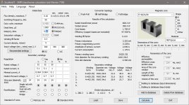
Using ExcellentIT I came up with a transformer design as follows:

EE42/21/20 N87 Core
Primary: 25 Turns (3 strands 24 AWG)
Secondary 1: 6+6 Turns (4 strands 24 awg)
Secondary 2: 6+6 Turns (4 strands 24 awg)
Auxilliary: 4 Turns(1 strand 24 awg)

Minimum output inductance for secondaries is 286.5 uH

For the input stage I am using a voltage doubler setup with 4 X 680uF capacitors rated at 400V and 3.3A ripple current
I will most likely be borrowing filter components and rectifier bridge from a donor supply on hand (rated at 1kW)

Here are the parts I have selected so far:
Main Switches: https://www.digikey.com/product-detail/en/stmicroelectronics/STW42N60M2-EP/497-15883-5-ND/5357092
Bulk Capacitors: https://www.digikey.com/product-detail/en/united-chemi-con/ESMR401VSN681MR45S/565-4480-ND/5824683
Transformer Core: https://www.digikey.com/product-detail/en/epcos-tdk/B66329GX187/495-5439-ND/3914756
Transformer Bobbin:
Output Diodes: https://www.digikey.com/product-detail/en/ixys/DSA30C150HB/DSA30C150HB-ND/1994931
Output Chokes: https://www.digikey.com/product-detail/en/bourns-inc/1140-331K-RC/M8380-ND/774920
Output Bulk Capacitors: https://www.digikey.com/product-detail/en/nichicon/LLG2C102MELZ40/493-7200-ND/3768538
Output Film Capacitors and Half Bridge coupling Capacitors: https://www.digikey.com/product-det...nic-components/ECW-F2W225JA/P14210-ND/1981482

Schematic: View attachment HalfBridgeSMPS.pdf
PCB Layout: View attachment HalfBridgePCB.pdf

Please let me know what you think and if there is anything I need to change.

Thanks,
Brady
 

Silvio

Well-known member
Hi Brady, I seen the schematic and I am a bit concerned about the inrush current at switch on 5 ohms against 120v gives a peak current of 24 amps will the bridge handle it?
I guess you will need some form of delay to let the bus caps charge up. I suggest you make another cap after R10 so that it will give some more time before the smps starts oscillation. I also see the the soft start cap on the SG3525 is rather small at 1uf, this may trigger your over current protection during the charge up of the secondary caps. What is your switching frequency? C34,C9 can be between 0.47uf to 1uf. dynamically the value doubles (2 X 0.47 = 1uf) however for 350 watts 1-2uf is rather enough. you can also use only one cap from the center tap of the bulk caps (see ATX smps) I suggest that you try things out on prototype board first before etching the pcb thus if any changes are needed you can alter things before making the final design. Everything else seems ok for me. BTW can you post a pic of Exellent IT calculations for your smps?

regards

Silvio
 

Silvio

Well-known member
Hi Brady, I seen the schematic and I am a bit concerned about the inrush current at switch on 5 ohms against 120v gives a peak current of 24 amps will the bridge handle it?
I guess you will need some form of delay to let the bus caps charge up. I suggest you make another cap after R10 so that it will give some more time before the smps starts oscillation. I also see the the soft start cap on the SG3525 is rather small at 1uf, this may trigger your over current protection during the charge up of the secondary caps. What is your switching frequency? C34,C9 can be between 0.47uf to 1uf. dynamically the value doubles (2 X 0.47 = 1uf) however for 350 watts 1-2uf is rather enough. you can also use only one cap from the center tap of the bulk caps (see ATX smps) I suggest that you try things out on prototype board first before etching the pcb thus if any changes are needed you can alter things before making the final design. Everything else seems ok for me. BTW can you post a pic of Exellent IT calculations for your smps?

regards

Silvio
 

brady

Member
Hi,

According to the datasheet for the diode bridge, it should be able to handle a surge current of over 200A for two cycles so it should be fine. I have a 1 ohm ICL on hand but probably will go ahead and order a larger one just to be safe.

The schematic has a 220uF capacitor on the auxilliary supply but I meant to change that to a 470uF capacitor. Will that solve the startup problem? Speaking of, I am trying to decide on a starter resistor value. I am unsure how much current the SG3525 will sink initially before it begins the first few pulses to start the auxilliary supply. I read somewhere that it draws 100mA idle. However, based on that value, I would need a start resistor of approximately 3300 Ohms but that would dissipate around 35 Watts which is unacceptable. I was considering using around 33k ohms as a compromise between losses and current but I don't know if that will start the controller or not. I suppose I will just have to try it out and see? I suppose I could tap the resistor off of the center tap of the bulk capacitors to reduce losses. Would that have a significant effect on moving the voltage off center?

As far as the soft start capacitor, I am unsure on how to calculate the value that would best suit my needs, so I more or less chose it arbitrarily. The datasheet supplies the source current for that pin so how would you correctly use that information to get the appropriate startup time?

I am using a switching frequency of 50kHz.

I performed a simulation in SPICE with the center tap of the bulk caps directly connected to the transformer and it did not stay well centered, however with the two film caps as shown in the schematic not connected at the center tap of the bulk caps it self centered very well. I was hesitant to connect directly to the center tap due to the higher impedance of the aluminum caps. Thats my main reason for using C34 and C9.

Here is my ExcellentIT calculations:
ExcellentIT.jpg
 

Silvio

Well-known member
Hi Brady, here are some suggestions I would like you to try out
1 soft start capacitor start with 10uf and then you can lower or rise the value accordingly

2 for the primary start up power you can take a look at my first smps (A 350 watt smps based on Borisgo2 design) The PDF tells the whole story in what I encountered during the build. This shows a constant current source powering the chip before the aux power comes into play. This is made up of 2 small transistors and a couple of zeners and resistors which is far better than a large resistor. This also gives time for the bus caps to charge up before the trigger voltage of the SG (8v) starts oscillation. you can also make a bigger cap than 10uf which will give more time for the bus caps to charge near their full charge. This larger capacitor will also give more energy at startup for a few pulses until the aux supply comes into play. Just take a look and take the idea. If not understood I will explain how it functions.
Link http://www.diysmps.com/forums/entry...with-current-limiter-based-on-Borysgo2-design

3 Regarding calculations on Excellent IT seems ok apart that your minimal current is too low thus having a large ouput choke this will make your voltage drop. I guess you better rise this a bit say 0.5 amp for example.
Did you consider how the windings will fit in the bobbin does your 6 turns fit in a single layer? It is good practice to fit windings using the whole width of the bobbin trying not to overlap with a partial second layer as this will rise your mutual inductance. Try to play with numbers on Excellent IT to get the best match. Did you see my video on youtube winding small transformers for smps? see it you will get ideas during winding. The more you see the more you learn and avoid mistakes.

4 Take a look here and translate with google from Russian to English you will get ideas on the starting arrangement and other things too. Observe what others did in their smps. There are also videos near the end of the article showing several things you can learn from. I tell you I knew nothing about smps apart from a little basic knowledge but reading and serching here and there I learnt a lot of things.
LINK http://soundbarrel.ru/pitanie/IR2153_01.html

5 One last thing regarding the pcb layout I read in forums that keeping the chip close as possible to the fets will help for a cleaner signal to the fets and keeping low current traces away as possible from high current paths. Also try to keep traces parallel thus any stray coupling will cancel out.

6 Quote As far as the soft start capacitor, I am unsure on how to calculate the value that would best suit my needs, so I more or less chose it arbitrarily. The datasheet supplies the source current for that pin so how would you correctly use that information to get the appropriate startup time?

I simply don't know sorry for that, trial and error will get you there for sure. This value can vary from 1uf up to 47uf if I am not mistaken but seen it somewhere for sure.

7 Regarding the DC blocking cap in the center tap, here using 2 gets better performance then using only one hence minimizing stress on this capacitor thus dividing the load as all the current has to pass through it. Also using 2 caps can save space on the pcb as having only one bus cap (when using 230vac) rated at 400 vdc, but in your case you are using a 120v input and using the bus caps as a voltage doubler.

If you have any further comments feel free I will try to answer in the best of my knowledge

Regards,

Silvio
 

brady

Member
2. I'm not sure I understand the circuit. does the CC starter circuit stay on after use? I don't see the advantage over a simple resistor seeing as both will dissipate the same heat. I believe that if the control circuitry does not draw any current until reaching 8v for the SG3525, then a resistor should be able to handle the job. I noticed the aux supply in your design only has 10uF bulk capacitance. I was using 470uF and thought it might be too large. However, with such a large capacitance, it should supply enough charge to get the auxilliary supply going before the voltage drops below lockout on the SG3525 if I'm thinking correctly. Since the center tap on the bulk capacitors is hard wired and will not really move with asymmetric power draw (on 120v input, which I will not be using 220v input), I should be able to use a resistor from there to charge the aux supply, thus lowering losses to a manageable 1.5W with a 15k resistor (taking into account the steady state current with the zener limit of 20v, the voltage drop steadies to 150v and sinks 10mA, thus 1.5W). By the way, I decided that my aux supply voltage would be better off dropped to a nominal 15v max 20v to avoid overvoltage problems.

3. The purpose of this supply is general use, so no minimum load other than a dummy resistor will be supplied. dissipating 500mA results in quite a large loss unfortunately which is why I went with the numbers I did. Since I plan on adding regulation after getting the supply working in an unregulated form first, would the voltage drop be a problem? Honestly I have not put much consideration into windings fitting on the bobbin as your video shows (I found the video very informative by the way). I haven't actually purchased any of the components so I do not have the core bobbin and have not yet made the litz wire. I just assumed it would 'probably' fit being so few strands per winding.

5. I can see why that would make sense. However, in my case I am trying to make the power board readily compatible with a separate controller board to fit in headers. I am basing this the design of another professionally made power supply I have on hand that had similar traces to the mosfets. I may be able to get the traces closer to each other in a redesign after reducing the output capacitors to just two instead of four.

7. I found two 680uF capacitors with a higher RMS ripple current rating, however I find that it is difficult to find a combination of required ripple current and capacitance that works without going to the more extreme capacitors. based on the calculations I did from my reference book, the rms current is around 6-7A rms and approximately 4.2-4.9A rms for a doubler configuration. The caps I found are rated for only 4.05A RMS. I found some 1000uF caps also rated for 3.66A rms. The problem is, the larger you make the bulk capacitance, the larger the rms current. Any advice?

Sorry if some of my documentation has inconsistencies, I was back and forth on a lot of the values and neglected to change them. I also apologize for bombarding you with all of these questions!

thanks for all the help!
Brady
 

brady

Member
I did some rough calculation for the transformer fill and found that using the 4x24 AWG litz I can achieve about 15 turns per layer at a diameter of 1.65mm and 3x24 AWG can achieve 18 turns per layer at a diameter of 1.4mm. So with 2 layers of 4x24AWG and 2 layers of 3x24AWG and one layer of 1x24awg the total depth is about 6.6mm out of a total window space of about 6.8mm. Maybe I should move up to an EE47/20/16 core?
 
Last edited:

Silvio

Well-known member
cc starter this works by firstly waiting for the bulk caps to charge to 160v and then the 33k resistor starts charging the 10uf cap and stabilizes at 9.5volts. Oscillation will start and aux supply comes into action regulating the voltage to 13volts thus shutting down the CC starter

Regarding winding you can put the wires side by side and check what fits this way before changing to a larger core. I guess that core you chose is large enough.

regarding the output choke you do not need it to be as said by exellent It. output caps will filter as well at low currents I guess 100uH per rail will be fine.

For the input Caps as a rule of thumb 1uf per watt will suffice, that what everybody else uses but if you need a better smoothing you can go for 2uf per watt (see ATX)

For output caps you can go for something smaller then parallel to get better ESR. I was just wondering did you ever see an ATX supply from an old computer? take a look at these and take some ideas how components are fitted and what capacitance they use. One other thing are you going to run your smps at full load all day? what I am trying to say is you have to make a compromise regarding physical size and power demand of the whole smps.

Silvio
 

brady

Member
Okay, so I think I am going to use two of these for my input bulk capacitors instead of the original four: https://www.digikey.com/product-detail/en/epcos-tdk/B43540A9687M/495-6306-ND/3499626
And I found these I can use two in parallel on each output. They only have 73mOhm ESR which seems low to me: https://www.digikey.com/product-detail/en/nichicon/UPJ1J331MHD/493-15654-ND/2599241
I also changed the minimum current to 200mA in ExcellentIT which came up with about 92uH so I found this inductor which conveniently is a direct swap with my previous choice: https://www.digikey.com/product-detail/en/bourns-inc/1140-101K-RC/M8377-ND/774917

I have looked at many ATX supplies in the past but don't have any on hand at the moment. without going too much into detail I can guess that picking based on the corner frequency created by the inductor and output caps can be a starting point (output capacitance of 680uF and 100uH inductance results in a corner frequency of 620Hz which seems reasonable for response time).

As far as the size and power usage, my intended purpose is to use it in a variable bench power supply, so it will not be ran at full load for extended times. However, I would rather overdesign it just in case. Size is not a real concern for me unless it has a significant effect on performance, so having oversized components doesn't bother me. However, I am constrained to the size i can print to etch.

Do you think the replacement parts I listed above will work better?

I think I understand the starter circuit better now. How could I modify it to work on the 340v tap? could I replace the 160v zener with a ~330v zener and adjust the current limit resistor accordingly?
would I be better off with a bulk auxilliary cap around 100-200uF as opposed to 470uF?
 

fourtytwo

Leaving bad site ASAP!
Hi Brady, great effort here! My experience is high voltage SMPS have a nasty habit of blowing up under abnormal conditions so I do a bit of extra work to try and make them more robust.

I notice your current sensing is only in the tail of the lowside mosfet so there is nothing to prevent overstress of the high side mosfet nor core saturation during its conduction. I would normally use a current transformer in the primary circuit to ensure both half cycles are protected, this also helps to ensure flux balance and prevent center tap voltage wander.

Another related technique is to use a film capacitor in series between the center tap of the large capacitors and the primary, this has lots of effects nearly all beneficial, it limits the instantaneous s/c current, helps to swamp impedance mismatches between high and low side everything in the bridge and again helps to keep the ct voltage in the center of those large caps that are unlikely to have a high enough voltage rating to withstand rail to rail wander.

John
 

Silvio

Well-known member
Okay, so I think I am going to use two of these for my input bulk capacitors instead of the original four: https://www.digikey.com/product-detail/en/epcos-tdk/B43540A9687M/495-6306-ND/3499626
And I found these I can use two in parallel on each output. They only have 73mOhm ESR which seems low to me: https://www.digikey.com/product-detail/en/nichicon/UPJ1J331MHD/493-15654-ND/2599241
I also changed the minimum current to 200mA in ExcellentIT which came up with about 92uH so I found this inductor which conveniently is a direct swap with my previous choice: https://www.digikey.com/product-detail/en/bourns-inc/1140-101K-RC/M8377-ND/774917

I have looked at many ATX supplies in the past but don't have any on hand at the moment. without going too much into detail I can guess that picking based on the corner frequency created by the inductor and output caps can be a starting point (output capacitance of 680uF and 100uH inductance results in a corner frequency of 620Hz which seems reasonable for response time).

As far as the size and power usage, my intended purpose is to use it in a variable bench power supply, so it will not be ran at full load for extended times. However, I would rather overdesign it just in case. Size is not a real concern for me unless it has a significant effect on performance, so having oversized components doesn't bother me. However, I am constrained to the size i can print to etch.

Do you think the replacement parts I listed above will work better?

I think I understand the starter circuit better now. How could I modify it to work on the 340v tap? could I replace the 160v zener with a ~330v zener and adjust the current limit resistor accordingly?
would I be better off with a bulk auxilliary cap around 100-200uF as opposed to 470uF?

1) input bulk caps seems ok for the power needed
2) output caps I would go for something with a bit more capacitance like 1500-2000 total would be more adequate
3) you can also go for a second filter with another small inductor on the output (like ATX. small piece of ferrite rod around 5/16" with around 10 to 15 turns close wound) with a further small capacitance. This will make better filtering in reducing HF noise on the output.
4) 200ma as minimum current is more realistic (80-100uH) more practical and sure the chosen parts should work better.
5) Do not forget that you will have voltage drop on load and say 32 volts will approximately go down to regulate at around 24-26v loaded at 5 amps. I am talking through experience now. Voltage drop will be approx 15-19% at full load.
6) You can add another 90v zener in series with the existing 160v zener as caps do not need to charge up at full voltage. I also had around 320vdc input and 160v zener worked well. your set up will be with 160+90v going to the base of the cc bjt and a further 10 or 11v zener tied from the base to ground. This will wait for the bulk caps to charge at app. 250v then zeners start to supply voltage to the base and finally regulating the output to 10v less 0.6v loss in the junction of the bJT (mpsa 42) app 9.4 volts this voltage will start charging the small cap tied to the emitter to ground (app 10-100uf) this will take some more time and when threshold voltage is reached for the SG3525 (8v) starts oscillation. As soon as oscillation starts aux supply will supply voltage to this point and regulate it to 13volts this voltage is tied with another zener tied from emitter to ground. A suitable resistor in series with the aux supply must be chosen so that current is limited according to the 13v zener. this way your start up supply will be rock solid.

Regards

Silvio
 
Top