Help please with glitch in an half bridge inverter

wally7856

New member
Four secondary's was a surprise.

I personally do not think that transformer design will work. I think it will burn up.

Were do you buy your parts from. I would like to see what is available to you.

Do you have a pdf of the bobbin you are using. I want to see if the wires will fit.

It may be impossible to get all four secondary turns ratios to work to get the voltages you want without a secondary regulator. Is that a problem.

Do you have a spec you have to meet for hipot on the transformer, or an isolation spec.
 

obiwan

New member
Please refer to post #1 here:

Please see post #1 here with a previous reply.
(click over here)


I explained before that this is a regulated power supply. It needs 4 secondaries. Three of them for output voltages. There is a fourth that is a bias voltage for the TL494 self powering after startup.

Have yo seen my last post in which I gave you all the details about the transformer ? I have additional pictures but it is very late at night here and I intended to post them tomorrow.

Give a couple of minutes and I will upload.
 

obiwan

New member
We are not working on the closed loop yet. The circuit shown is just a very well known PWM generator in order to test all the power and driver circuits, and magnetics. We will close the regulation loop once the power section is finished. The circuit is driven with the typical TL494 scheme, working at 60 KHz

Remember that I explained this before ...
 

obiwan

New member
Four secondary's was a surprise.
I personally do not think that transformer design will work. I think it will burn up.
Were do you buy your parts from. I would like to see what is available to you.
Do you have a pdf of the bobbin you are using. I want to see if the wires will fit.
It may be impossible to get all four secondary turns ratios to work to get the voltages you want without a secondary regulator. Is that a problem.

Do you have a spec you have to meet for hipot on the transformer, or an isolation spec.


Have you read this previous post ?

http://www.diysmps.com/forums/showthread.php?755-Help-please-with-glitch-in-an-half-bridge-inverter&p=13320#post13320

We are using good quality parts from TDK and EPCOS, available locally. This doesn't mean that we have enough skills to wind a SMPS transformer manually.
Please see the link above and the pictures that I am attaching with the output screen from the calculation program. In previous posts I have shown all the secondaries calculations.
As I said, this is a regulated SMPS and YES it has 4 secondaries, the usual ones, low current.
Also, as I explained before, all the previous versions of this transformer with just one 12V secondary and with full 4A load, worked cool. The power MOSFET's also are working pretty cool.
I have previously shown a link with the complete data manual PDF document of the TDK / EPCOS ER35 core magnetics
You say that this will burn up. Please tell me why.
Here are the fotos while we wind the transformer.

Kind regards
 

Attachments

  • DSC05293.JPG
    DSC05293.JPG
    210.3 KB · Views: 10
  • DSC05294.JPG
    DSC05294.JPG
    212.4 KB · Views: 11
  • DSC05302.JPG
    DSC05302.JPG
    171.8 KB · Views: 10
  • DSC05303.JPG
    DSC05303.JPG
    176.1 KB · Views: 10
  • DSC05304.JPG
    DSC05304.JPG
    155.9 KB · Views: 10
  • DSC05305.JPG
    DSC05305.JPG
    164.2 KB · Views: 10
  • DSC05306.JPG
    DSC05306.JPG
    170.7 KB · Views: 10
  • DSC05309.JPG
    DSC05309.JPG
    161.1 KB · Views: 9
  • DSC05310.JPG
    DSC05310.JPG
    190.9 KB · Views: 11
  • Captura_64.jpg
    Captura_64.jpg
    366.2 KB · Views: 11

wally7856

New member
We definitely have a communication problem here. You think you answered these questions before and i have no idea why you are referring to posts that do not apply.

I personally do not think that transformer design will work. I think it will burn up. Because of the wire diameter, i think your 4A winding is only good for 1.5 to 2 amps.

Were do you buy your parts from. I would like to see what is available to you.

Do you have a pdf of the bobbin you are using. I want to see if the wires will fit. The bobbin is also called the coil former. It is the plastic thing you wind the wire on.

It may be impossible to get all four secondary turns ratios to work to get the voltages you want without a secondary regulator. Is that a problem.

Do you have a spec you have to meet for hipot on the transformer, or an isolation spec. This spec should be in the kilo-volt range as high as 3.7 KV or so.

The pictures are a little hard to follow. You should have at least 5 total windings and i only see 4.
 

obiwan

New member
OK, yes we have a communications problem here.
Why are you skipping the information that I am posting for you ?
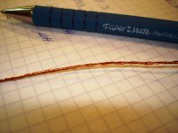
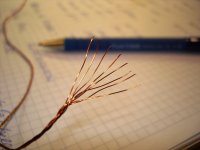
How come an 8 * 0.3mm wire will burn with 4A current ?
I told you before that the transformer tested with just one 12V secondary ran cool at full 4A load for hours.
I think that you are going too fast and you are skipping lots of information that I've been uploading for you to evaluate.
Definitely you are not reading all the material that I can clearly see in the thread index (upper part ), going thread by thread.
Everything you have been asking is there.

For example:

1. you asked for the kind of materials we are using - I replied in detail with a complete manual in PDF format
2. you asked for the transformer calculation - I replied to you with primary and secondary winding details, number of turns, number of wires.
3. you asked about the output inductor - I replied with the inductance of the 4 inductors and winding details
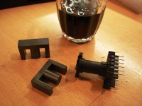
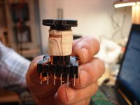
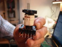
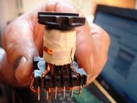
4. you asked about the core used in this transformer - I replied that was ER35/22/11 TDK/EPCOS, and picture of the forms and ferrites, permeability figure, N27 material
5. you advised that a regulated SMPS was needed for 4 secondaries, I replied twice (one quoting your text) that this must be a regulated SMPS and the reason why I am NOT closing the loop yet
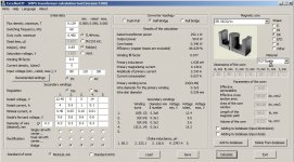
6. at least 3 times you asked about the transformer calculation and I uploaded at least 3 times the output screen of the program that I am using, with ALL the input parameters, voltages, currents, frequency, core, etc, and the outpit, which includes power rating of the core, power used, winding info for the primary, n turns, number of multifilar wires and diameter, same for all the secondaries, and all the inductance values for the 4 output filters, all in one single screen.

To get things in order, I suggest then you make on question and I give an answer to that question if you agree.

I catched you last post in my cell phone by my bed and, as I don't like to disappoint you, I got up for giving you a reply. If you don't mind I will get back to bed, it is 2 am here.

Thank you and kind regards
 

wally7856

New member
Your English is very good so i do not understand why we can not communicate. I was very careful with post 25 to make it easy to understand and you could not. From your next post i see almost everything i say or ask you are not understanding. It is to much work for me to go over everything in painstaking detail, i can not help you.
 

obiwan

New member
It is to much work for me to go over everything in painstaking detail, i can not help you.

Never mind, in practice and to be honest, you never did.
Good to know you are a Senior member Guru, nice example
:"::
Thank you anyway for the try.
Semper Fi !
 
Top