You are using an out of date browser. It may not display this or other websites correctly.
You should upgrade or use an alternative browser.
You should upgrade or use an alternative browser.
I'm searching of IR2153_SMPS in 300W
- Thread starter koyane
- Start date
I've tried to make it, but every time failed.
I want to see good working IR2153_SMPS. And and want to touch and feel it in my hand.
If some one has it, I'd like buy it. Please contact me.
email:jacobku06181@gmail.com
I'm waiting.
Have you built some SMPS units before?
Thank your reply, MicrosiM
Yes, I did. I made 20 more. and I have many dead parts now.
First, MJE13005, 1 TR Flyback. Succeed. But I want half bridge which need no gab. Gab is not easy to me.
Second, IR2153, almost 20 more times, 20 more schema. Recently I recognized I confused the difference of type D and S.
After that IRF840 surived. I used IR2153D, but connected a diode the place between 1 pin and 8 pin. that was the reason to kill the a cup of IGBTs.
And Big CAP killed the IGBT too. Now I use 20 uF 400 volt. Still now I feel horror when I feed electricity initially.
I my smps made very today, failed too. It gave me Only 1 volt DC out. Big toroidal core trafo, pri 24 turn, Sec. 10 turn.
The reason to use troidal core, I wanted to know what turns is better to get high voltages.
I tabbed every turn to be easy to change the turns. Yes, I got it. 6 th turn makes 1.1 volt. 5 th and 7 th 0.7 volt. others are 0.5 volts.
I couldn't believe this. I must wind 2000 turns for 200 volts. This is wrong. But I got such this low voltages sever times. I don't know why.
Ofcouse I winded ei core TDK40 11+11 on pri, 96 turn on sec. I got only 5 volt. I want to send it to someone who could fix it, if there is who.
Ir2153 passions passed 3 years ago in this site.. Nobody makes it todays. And I'm sick of IR2153, My head is headache , but my mind doesn't give up ir2153.
So my head deal with my mind, OK, buy one working IR2153 and make your own one as same as it.
This is the story.
Dear microsiM, do you have one ? Please sell it me. I want to buy that..


Thank your reply, MicrosiM
Yes, I did. I made 20 more. and I have many dead parts now.
First, MJE13005, 1 TR Flyback. Succeed. But I want half bridge which need no gab. Gab is not easy to me.
Second, IR2153, almost 20 more times, 20 more schema. Recently I recognized I confused the difference of type D and S.
After that IRF840 surived. I used IR2153D, but connected a diode the place between 1 pin and 8 pin. that was the reason to kill the a cup of IGBTs.
And Big CAP killed the IGBT too. Now I use 20 uF 400 volt. Still now I feel horror when I feed electricity initially.
I my smps made very today, failed too. It gave me Only 1 volt DC out. Big toroidal core trafo, pri 24 turn, Sec. 10 turn.
The reason to use troidal core, I wanted to know what turns is better to get high voltages.
I tabbed every turn to be easy to change the turns. Yes, I got it. 6 th turn makes 1.1 volt. 5 th and 7 th 0.7 volt. others are 0.5 volts.
I couldn't believe this. I must wind 2000 turns for 200 volts. This is wrong. But I got such this low voltages sever times. I don't know why.
Ofcouse I winded ei core TDK40 11+11 on pri, 96 turn on sec. I got only 5 volt. I want to send it to someone who could fix it, if there is who.
Ir2153 passions passed 3 years ago in this site.. Nobody makes it todays. And I'm sick of IR2153, My head is headache , but my mind doesn't give up ir2153.
So my head deal with my mind, OK, buy one working IR2153 and make your own one as same as it.
This is the story.
Dear microsiM, do you have one ? Please sell it me. I want to buy that..
Hello.
First thing I recommend that you calm down.
Then please check this thread
http://www.diysmps.com/forums/showt...ith-short-circuit-protection&highlight=IR2153
It contains a working SMPS using IR2153, and as you can see its a basic SMPS, I strongly recommend that you read the PDF here
http://www.diysmps.com/forums/showthread.php?72-Necessary-Equipments-needed-for-SMPS-development
I noticed in your schematic, tha you dont have a diode between PIN 8 and PIN 1 of the IR2153 ????? your SMPS will never work without that diode.
Do you have oscilloscope?
Last edited:
res_smps
Member
Second, IR2153, almost 20 more times, 20 more schema. Recently I recognized I confused the difference of type D and S.
IR2153D has an internal bootstrap diode (50ns 250mA), IR2153(S) doesn't
with big cap you need softstart circuit (i use NTC 47D-15) then bypassed with relay, maybe you can try with 50 to 100 ohm 10W resistor
a 100W light bulb in series with mains input voltage might save your fet/igbt when testing your smps
this is my schematic View attachment ir2153-updated2.pdf
blasphemy000
New member
The up-arrow on the one lead of your current sensing transformer and the down-arrow on the lead of the bottom primary winding, are those two arrows connected in your circuit? If so it's creating a dead short across that small portion of the primary winding.
res_smps
Member
Thanks MicrosiM.
And res_smps, Thanks too.
OK, I'll try on ur recommend.
But, my post which wanting working IR2153_SMPS would be effect until to get anyone's apply, and am waiting.
this is my smps with above schematic
https://www.youtube.com/watch?v=ZmbQ07JOGqs
Hi, MicrosiM. I'v a 40 Mhz Oscope. And I'm studying in the threat norazmi starting. All of articles are very useful threats.
All members are helping me make working IR2153_SMPS. This time I believe I could hit it.
I appreciate this site and MicrosiM. Thank u so much, MicrosiM.
All members are helping me make working IR2153_SMPS. This time I believe I could hit it.
I appreciate this site and MicrosiM. Thank u so much, MicrosiM.
this is my smps with above schematic
https://www.youtube.com/watch?v=ZmbQ07JOGqs
Hi, res_smps. You'v seen my schema. What's wrong with my smps?
Has it trafo problem ?
I have a TDK EI40 core. I posted the core's spec above.
could u design my trafo please? I need two way out, 200 volt DC/0.5A, and 40 volts/ 1 A.
2 x IRF840 are enough. No more IGBTs. Your smps is too big for me.
I offer you.
If you assemble it with following spec, I'll pay 99 us $ including shipping charge.
TDK EI40 core and IR2153D and relay, two IGBTs of IRF840.
No need case and cable. Only assembling parts on the PCB(proto board is OK)
am waiting ur reply.
res_smps
Member
The store selling relay displayed so many products. Would u please let me know the spec of u used ?
songle SPDT relay 24v 10A , but you can use other type
Hi, res_smps. You'v seen my schema. What's wrong with my smps?
Has it trafo problem ?
I have a TDK EI40 core. I posted the core's spec above.
could u design my trafo please? I need two way out, 200 volt DC/0.5A, and 40 volts/ 1 A.
2 x IRF840 are enough. No more IGBTs. Your smps is too big for me.
I offer you.
If you assemble it with following spec, I'll pay 99 us $ including shipping charge.
TDK EI40 core and IR2153D and relay, two IGBTs of IRF840.
No need case and cable. Only assembling parts on the PCB(proto board is OK)
am waiting ur reply.
i have no experience using current sense transformer but i think that is not correct (as blasphemy000 said in post #8), may be it should like this

you can use excellentIt software (please search this forum) to calculate your trafo or you can use this formula
Np = 0.5*Vin(DC)*10^8/(4*Bmax*f*Ac)
Np : number of primary turn
Vin(DC) : mains AC voltage x 1,4 (310vdc for 220v mains)
f : frequency in Hz
Ac : effective cross sectional area in cm2 (see core datasheet)
Bmax = maximum flux density (try from 1000 to 2000) start from 1500, if trafo getting hot try lower Bmax
and I am sorry I cannot help you assembling your smps, maybe someone here can help you
from my experience bulding smps with IR2153, soft start circuit (NTC or resistor bypassed by relay) is a critical part to protect your mosfet/ir2153 chip
Thanks a lot u showed the formula and the curr_sense_prt part where I misunderstood, and corrected the schema.
If u cocern the part, why don't u make that without the relay part. It dosen't matter.
I only long to see working SMPS made by IR2153, every one turn of sec make 4 ~ 6 volts.
In this formula
My Np=0.5 * 310 * 10^8 / 4 * 1500 * 100 * 1.44(I measured myself this)=17.94
OK. I'll remake mine using this result 18 turn.
So, this time I make such like this : pri is 18 + 18 :sec is 10 turns (purpose is to see what voltages come out. Expecting 40 ~60 volts)
And then let's talk about assembling matter again. thanks res_smps
res_smps
Member
the circuit also protect circuit breaker in my house from trip when I switch on smps (from inrush current charging primary caps)If u cocern the part, why don't u make that without the relay part. It dosen't matter.
i use 1000uf x2 on primary
you only need 18 turn not 36OK. I'll remake mine using this result 18 turn.
So, this time I make such like this : pri is 18 + 18 :sec is 10 turns (purpose is to see what voltages come out. Expecting 40 ~60 volts)
wind 9 turn primary, all secondary, then 9 turn primary, aux
with 10 turn secondary and 18 turn primary you will get ~86v without load
1st layer 8 t
2nd layer 9 t
3rd layer 10 t
4th layer 10 t
5th layer 9 t
6th layer 8 t
I could test several combinations.
I put that rewinding trafo up the board. And tested. I got same result. It's meaning failed.
so, I' m assembling another one on the proto board. Tomorrow I'm going to wind current trafo.
Thanks, res_smps.
Hi, res_smps and all guys.
I got around 80 VDC. from new assembled card this morning 2 o'clock in Tokyo and Seoul time.
But I was not sure exactly what VDC came out, because I turned off soon, seeing the moving hand up to around 80 VDC.
While seeing the meter hand of DC volt, the assembly made smell and smokes. I thought it happened in 5 seconds. I thought the resistor couldn't alive which was protecting in rush current, 100 ohm of 10 W.
I had put that R between NTC and recti diode KBU808.
I bravely(fool) took out the resistor and connected NTC and KBU808. And turned on. And I saw a bright light in the fuse box.
What is the best thing I do?
changing FUSE, IGBTs then what ?
I used 1.5 A fuse. Should I use bigger one, such like as 5A ?
res_smps
Member
Hi, res_smps and all guys.
I got around 80 VDC. from new assembled card this morning 2 o'clock in Tokyo and Seoul time.
But I was not sure exactly what VDC came out, because I turned off soon, seeing the moving hand up to around 80 VDC.
While seeing the meter hand of DC volt, the assembly made smell and smokes. I thought it happened in 5 seconds. I thought the resistor couldn't alive which was protecting in rush current, 100 ohm of 10 W.
I had put that R between NTC and recti diode KBU808.
I bravely(fool) took out the resistor and connected NTC and KBU808. And turned on. And I saw a bright light in the fuse box.
What is the best thing I do?
changing FUSE, IGBTs then what ?
I used 1.5 A fuse. Should I use bigger one, such like as 5A ?
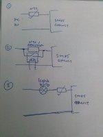
if using resistor it should be bypassed using relay 2 or 3 second after startup
sorry my english is not good so i will explain using picture
see attached picture,
1. for low power smps you can use NTC without bypass relay
2. high power smps needs relay to bypass NTC/resistor
3. at first time, you should connect light bulb (like this http://en.wikipedia.org/wiki/Incandescent_light_bulb) not a lamp with electronic circuit inside
wihout any load connected to smps, when you switch on your smps you will see that bulb will light on a second an then light went out. that means your smps is ok
but if the lights are still lit continuously mean your SMPS circuit is not correct
and make sure you are using ungapped core
Attachments
-
 CAM00125_1.jpg59.2 KB · Views: 19