You are using an out of date browser. It may not display this or other websites correctly.
You should upgrade or use an alternative browser.
You should upgrade or use an alternative browser.
I'm searching of IR2153_SMPS in 300W
- Thread starter koyane
- Start date
Hi, res_smps.
Thanks, u explained using picture. So am I in poor English.
I used NTC 5D-11 taken from old computer PSU. but I'll use NTC47d-15, U USED.
I thought it was AC voltages in front of NTC. But u said DC voltages in the picture above number 1.
Ok. I'll use the relay u told before, the model that u used, SPDT24V10A.
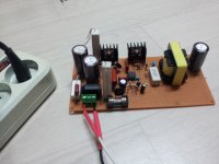
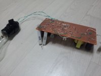
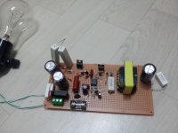
This is my new assembled IR2153_SMPS.
When I tested initially I saw high voltage i wanted very short moment, maybe 5 seconds. And a resistor smoked.
Today I tried a 200w light bulb connecting. But I only saw bulb's winking 3 ~5 sec., I expected this SMPS to stop winking. Then this bulb stopped her winking and then lighting the room.
Suddenly, I realized the winking's meaning is a signal to turn off electric switch.
I couldin't see the high voltages what I had seen last time. I totally confused. What's wrong. This half bridge is very simple schema, several components. There's no place to hide special knowhow.
But I couldn't mak this.
I'm still searching someone who make this for me. Or who fix my smps in this picture. This schema is norazmi's posting.
I would like to pay him 99 us $.
Please email me.
email: jacobku06181@gmail.com

lynxlynx
A rumbling soft motor
@koyane
ir2153 datasheet includes typical usage circuit, do you understand how it works? Google also finds many of them.
I for self had only once used ir2153 in incompatible mode as push-pull driver and oscillator in same case
The problems were:
- "high" switch was always more hotter than "low",
- switches often burned without gate-to-source 1k resistor,
- much of no-load current (I was seeking for a quick circuit to be my first solar inverter),
- completely no regulation (I was hit once by it's 400VDC at no load)
- ir2153 start-stopped when there was a "magic voltage", resulting in load "blinking".
Because I used it not as intended I then disassembled thing when I got an advanced sg3525 working.
I also had partial "success" with two of them building a full bridge with circuit as shown there: http://hobbyelektro.eu/zdroje-menice_stridac.php. While it worked fine for low voltage (and still it serves to me as a ferrite frequency tester with two trimmers), I tried to adapt it to high voltage so I can get a very cheap MSW inverter but it only burned remaining 8 IRF740 I had (circuit worked fine even for a day and then suddenly - boom! haha, that was irritating, and that was with shared ground between generator and this circuit). From there I did not experimented with it. Actually complete lack of regulation stops me from doing any experiments with it.
So, aside from that I recommend you now to redraw the schematic from your assembled circuit, tracing any connections to parts. That always helped me when I was in trouble! And then post your result here, maybe I can help (although not a very big specialist of ir2153 I probably understand how half bridge works)
ir2153 datasheet includes typical usage circuit, do you understand how it works? Google also finds many of them.
I for self had only once used ir2153 in incompatible mode as push-pull driver and oscillator in same case
The problems were:
- "high" switch was always more hotter than "low",
- switches often burned without gate-to-source 1k resistor,
- much of no-load current (I was seeking for a quick circuit to be my first solar inverter),
- completely no regulation (I was hit once by it's 400VDC at no load)
- ir2153 start-stopped when there was a "magic voltage", resulting in load "blinking".
Because I used it not as intended I then disassembled thing when I got an advanced sg3525 working.
I also had partial "success" with two of them building a full bridge with circuit as shown there: http://hobbyelektro.eu/zdroje-menice_stridac.php. While it worked fine for low voltage (and still it serves to me as a ferrite frequency tester with two trimmers), I tried to adapt it to high voltage so I can get a very cheap MSW inverter but it only burned remaining 8 IRF740 I had (circuit worked fine even for a day and then suddenly - boom! haha, that was irritating, and that was with shared ground between generator and this circuit). From there I did not experimented with it. Actually complete lack of regulation stops me from doing any experiments with it.
So, aside from that I recommend you now to redraw the schematic from your assembled circuit, tracing any connections to parts. That always helped me when I was in trouble! And then post your result here, maybe I can help (although not a very big specialist of ir2153
Last edited:
I redrew the schema of the assembly. and found 1 point. It was pin no. 7. I forgot to welding.
And tested.the bulb doesn't make the light.
The voltages of no.1 pin is 13 volt. And Output DC volt is too low.0.2 volt.
This stuff returned lower volt, less than 1 volt.. again.
I want to see smoke and smell.
Special thing is that the pin no.1 is a motor-boating voltage. don't know.
And tested.the bulb doesn't make the light.
The voltages of no.1 pin is 13 volt. And Output DC volt is too low.0.2 volt.
This stuff returned lower volt, less than 1 volt.. again.
I want to see smoke and smell.
Special thing is that the pin no.1 is a motor-boating voltage. don't know.
I'm a Korean. and uncomfortable speaking English.
7 pin had welded when I initially fed electricity it and smelled and smoked.
But this time while I redrew it I discovered that I found there is a little gab between the wire and the spot of 7 pin.
I'm not sure if some heat occurred in there.
And I removed the NTC5D-11 and put a DSC10D-9 in the place newly.
The noticeable thing now is there to be motor-boating in OUT DC POWER, 0.2 volt.
Every situation returned the beginning point when I posted first time this site.
Now I missed the time I saw the smoke.
Was it a piece of dream I saw the smoke?
No, I'm sure I saw the smoke on the assembly and I posses the burned resistor. that time the hand of ampere meter going up to around 80 volts.


