Inverter based on a balanced class D amplifier 500W - 1000W, feedback after filter.

Inno3D

New member
Dear all,

In order to make an accurate 60Hz voltage inverter I'm trying to bases this on a balanced class D amplifier 500W - 1000W, Based on a self oscilating PWM amplifier with a very low output impedance. The most important is that the feedback is after the filter, (in order to be independant of the load). It's discriped by Hypex aswell, here;

http://www.hypex.nl/technology/ucd.html

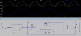
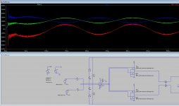
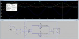
I have made a full schematic already, but fiirst now I tried it to simulate with LTSpice. Unfortunatly not very succesfull.

In the simulator schematic I replaced the FET's incl. driver's by a controlled voltage source. The input's are simply sine wave sources, 180 deg phase shifted, and directly connected to the comparator. Mainly I try to get the feedback correctly.

Is there anyone who can give advise? I uploaded the full pdf of the schematic. Also the LTSpice schematic which I do not get to simulate correctly.

The LTSpice file i had to rename otherwise the forum didn't allowed it to upload. Please rename the file rename_asc.pdf to ltspice.asc
 

Attachments

  • Inverter_UCD.pdf
    62 KB · Views: 582
  • rename_asc.pdf
    5.8 KB · Views: 301

Inno3D

New member
for the TinaTI users I also have made a schematic (because I did not trusted the simulation results of LTSpice). There is still a problem in the inverter of the negative path. This one seems not to invert..

please rename the file rename_tsc.pdf to schematic.TSC This was because the forum didn't allowed me to upload a tsc file.
 

Attachments

  • rename_TSC.pdf
    19.1 KB · Views: 238

MicrosiM

Administrator
Staff member
Inno3D

Welcome to the forums.

I really like the idea of this project. But indeed its going to be tricky

Hypex claim they designed it, but in my opinion everything is taken from B&O (ICEPOWER) main invention. I am working at similar project at the moment (self oscillating CLASS-D 1KW) I even don't know if it will work properly (4 Layers PCB)

But i am not sure yet how you will implement this into the inverter, is it going to be supplied from 220V? or 12V?

Can you tell me what problem you are facing?

Regarding the upload, you can ZIP the files and upload them!

Good luck
 

Inno3D

New member
Thank you for the warm welcome!

I am making 230Vac @ 60Hz from a 400Vdc power supply (but it might work at 220 aswell, the input signal amplitude can be varied to fit the output amplitude in between the voltage rail).

Today I have finally got the TinaTI simulator running on the circuit. Somehow it seems to have less trouble simulating, compared with LTSpice, although the graph display is bit less convenient.

The self oscillating part seems to work out ok as long as it operates where it should. And that's exactly where I stand at the moment. Finding the right signal level / dc offset. Also determining the loop gain, filter L / C values and loop bandwith.

I already made in hardware the balanced input 60Hz sinus. But after this I went to the simulator. How are the lab testing working out for you?

Attached latest TinaTi ZIP file (thank you ;-)

This one seem to have the at least the overall implementation correct, since oscillation seems working ok. Some simulations do show a need pwm signal following the input.

Conform the subscription of Hypex the next thing to do is set the switching freq. 10x corner freq of the filter At this frequency the phase lag of the output filter is very nearly 180 degrees, pretty much irrespective of the attached load. Oscillation occurs at the frequency where phase shift is exactly 180 degrees.

Are you any good in this?

Do we have a similar implementation? balanced UcD? feedback after the filter?
 

Attachments

  • 50HzInverter.zip
    6.2 KB · Views: 210

Inno3D

New member
Dear MicrosiM, I have finished a LTspive simulation which seems to be very hopeful. I found out how to do differential measurement in LTspice. I attached a screenshot from the simulation displaing the Vac+ Vac- to gnd (green, purple)) and the differential Vac +,- (blue). (I wouldn't have told blue was the outcome!). At least here is 240Vpp 60Hz. And I believe quit independent of the load.
 

Attachments

  • wave.jpg
    wave.jpg
    170.6 KB · Views: 141

Inno3D

New member
This simulation I improved the model of the push pull stages. Current plot is at ca 750W, 264Vpp in 50 Ohm load. Output is having some distortion over 500W but it might be possible to tune the feedback.
 

Attachments

  • 60Hz_rev19.jpg
    60Hz_rev19.jpg
    200.2 KB · Views: 60

MicrosiM

Administrator
Staff member
Looks nice to me what you have just got.

I will download those files soon to my PC, and check the simulation also


only problem I cannot show some of my simulations. is that I cannot find LM319 in the LTspice.

I wanted to simulate my CLASS_D amplifier before sending to Fabrication.

But everything looks normal for now, But I still think there is lot of work, specially the high voltage side
 

Inno3D

New member
Finally I used a Vcc of 10Vdc on the comaparator. This way there is some bit more head-space, at the inputs, caused by the drift in the feedback. For the LM319 10Vdc is not an issue. One part that I'm still not sure about is switching speed. Switching too fast may cause the FET's getting too hot, definitely <100kHz. The LM319 response time is 80ns, also for the LM319 there must be a bandwidth limit in response time as well. To my opinion the pulses in the simulation are still to high in frequency. This must be done in the feedback... Also I think we need some exotic FET's to switch Ids currents effectively. What FET's did you design-in? what gate currents do you anticipate?
 
Top