MyFirstSMPS
New member
As my previous tests IR2153 driver was not successful, I gave up on this chip and chose the second approach - SG3525 and IR2110 gate driver. The first test was done with them after some rooting around on the web and came across a simple option - http://eletronicasilveira.forumeiros.com/t4135-fonte-chaveada-com-sg3525-2-versoes
Then I tried to put together but once again I met a new problem arising from the IR2110 driver. Specifically, this driver bootstrap circuit - namely, I can not Hi-OUT signal, Lo-OUT works but playing different bootstrap capacitor capacitances does not work Hi-OUT - the Hi-output does not react completely, scope does not give any picture - it does not seem to output exist.
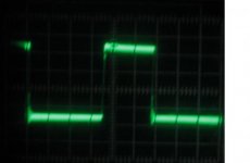
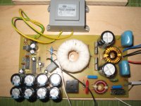
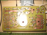
I will add a few pictures, the first IR2110 Lo-OUT output scope image and the others are power supply images of the PCB from the parts side and the bottom. Can anyone suggest what I should still try to get both outputs to work properly?

1:1 probing IR2110 Lo-OUT
1uS/div.
2V/div.


Then I tried to put together but once again I met a new problem arising from the IR2110 driver. Specifically, this driver bootstrap circuit - namely, I can not Hi-OUT signal, Lo-OUT works but playing different bootstrap capacitor capacitances does not work Hi-OUT - the Hi-output does not react completely, scope does not give any picture - it does not seem to output exist.
I will add a few pictures, the first IR2110 Lo-OUT output scope image and the others are power supply images of the PCB from the parts side and the bottom. Can anyone suggest what I should still try to get both outputs to work properly?

1:1 probing IR2110 Lo-OUT
1uS/div.
2V/div.


Last edited:
