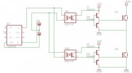
The optoisolator circuit shown above will not work for the following reasons:
-Both the drain and source of the lower FET are shorted together and grounded, so it's as if the lower transistor is always on.
-If the upper FET turns on, the input voltage is shorted to ground, high currents flow as in a shoot-through condition, things go boom.
-The switching volt-seconds of high and low side is asymetrical, therefore the transformer will saturate and more things go boom.
-The totem pole driver is unable to turn on a high side FET as it doesn't lift the gate voltage above the drain voltage. You would need some kind of bootstrapped power supply to provide a voltage higher than the input voltage. This would be complicated if using an optoisolator to transmit the signal as it can't transmit any power.
-Optoisolators don't really have the bandwidth to transmit a square wave at a realistic switching frequency with any fidelity (especially not all the odd order harmonics which make it square). resulting in excessive switching loss and fried semiconductors.
-555 timers have no place anywhere near a SMPS (at least not as the switching oscillator).
High side gate drive is done with either a high side gate driver IC or a gate drive transformer.
There are ICs to drive high and low side gates in phase or antiphase with eachother and also the IR2153 has a built in high and low side gate driver, but driven from an internal oscillator at a fixed maximum duty cycle rather than having a low side PWM TTL input like a proper gate drive IC. Gate drive ICs use a bootstrap system to provide high side power since to turn a FET gate on.
Gate drive transformers are relatively simple devices that can have quite a high bandwidth ensuring a good quality gate drive signal if properly designed. The totem pole driver would be on the low side input since power is transmitted across the isolation, as would the gate resistor and depending on the driving topology, a coupling (DC blocking) capacitor.