IR2153 question

twenglish1

New member
I am starting to design my first smps, and I choose to use the IR2153 pwm driver, I will be using it to drive a half bridge igbt module, I am aware that the high and low side gates of these modules need to be driven from power sources that are isolated from each other, will this chip provide that?
 

twenglish1

New member
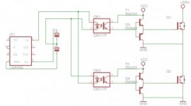
That's what i meant, well back to my question, using the drive method shown in the schematic i was told that the high and low side gate drive transistor pairs need to be connected to two separate supplies that are isolated from one an other, does this driver chip provide this isolation?
 

Attachments

  • 555 half bridge.jpg
    555 half bridge.jpg
    16.9 KB · Views: 183

twenglish1

New member
Here is what I was told about driving an igbt module using the schematic posted above:
"Think about it, with one power supply for both gates, the negative of the gate drive power supply is tied to the negative of the high voltage power supply by way of the lower IGBT's emitter. The upper IGBT also has an emitter, which also needs a reference with a power supply. If you use the high voltage negative as the reference for both IGBT gate drivers, the your gate drive power supply now has interface at it's negative output with the high voltage negative, and the high voltage positive. When the upper IGBT switches on, this effectively connects it's own emitter to the high voltage positive. This will lead to catastrophic failure, as the DC bus capacitors will discharge through the gate drive power supply whenever the upper IGBT switches on. So yes you will need separate power supplies for your gate drivers"
 

demykiko

Member
Hi twenglish1,

Its better to use opto isolator with a high frequency capability that can handle 100khz without loosing good pulse shape..
Good pulse shape has really something to do with the success of any SMPS.

Regards,
Demykiko
 

KX36

New member
The optoisolator circuit shown above will not work for the following reasons:
-Both the drain and source of the lower FET are shorted together and grounded, so it's as if the lower transistor is always on.
-If the upper FET turns on, the input voltage is shorted to ground, high currents flow as in a shoot-through condition, things go boom.
-The switching volt-seconds of high and low side is asymetrical, therefore the transformer will saturate and more things go boom.
-The totem pole driver is unable to turn on a high side FET as it doesn't lift the gate voltage above the drain voltage. You would need some kind of bootstrapped power supply to provide a voltage higher than the input voltage. This would be complicated if using an optoisolator to transmit the signal as it can't transmit any power.
-Optoisolators don't really have the bandwidth to transmit a square wave at a realistic switching frequency with any fidelity (especially not all the odd order harmonics which make it square). resulting in excessive switching loss and fried semiconductors.
-555 timers have no place anywhere near a SMPS (at least not as the switching oscillator).

High side gate drive is done with either a high side gate driver IC or a gate drive transformer.

There are ICs to drive high and low side gates in phase or antiphase with eachother and also the IR2153 has a built in high and low side gate driver, but driven from an internal oscillator at a fixed maximum duty cycle rather than having a low side PWM TTL input like a proper gate drive IC. Gate drive ICs use a bootstrap system to provide high side power since to turn a FET gate on.

Gate drive transformers are relatively simple devices that can have quite a high bandwidth ensuring a good quality gate drive signal if properly designed. The totem pole driver would be on the low side input since power is transmitted across the isolation, as would the gate resistor and depending on the driving topology, a coupling (DC blocking) capacitor.
 
Last edited:

demykiko

Member
Very nice KX36..well explained..I'm now assembling my own GDT using ee16 core..
Can you give suggestions as to why the pulses of hand-made GDT is not so perfectly good in shape as
compared to the pulses of IR2153..Thanks

Regards
Demykiko
 

demykiko

Member
ah ok thanks..although I'm using EE16 core without gap, I'll give a try the small toroid you mentioned. Can I use the toroid found inside the CFL(compact fluorescent lamp)as GDT? I'm sure green toroid and yellow toroid from ATX PSU are not suitable coz they are powdered iron core, If I'm not mistaken?

Regards
Demykiko
 

twenglish1

New member
i have taken some time away from this project, i tend to get into situations where i have many projects going on at once, last i did with this project was i had been experimenting with the SG3525 as a means of handling output feedback and providing the signals for the gate drive transformer, i had experimented with a few designs of transformer but to no success with getting a good clean output, i had talked to some people in another thead and my problem was my method of driving the transformer, and that is about where i left off with my project.

@demykiko: i am not sure if that core will be suitable either, as far as i have known just about all you can do is wind it up and test it with a scope, cores are usually unmarked, at least the ones i have experimented with
 

demykiko

Member
Ok thanks twenglish1..I don't have yet experience with the toroid as suggested by KX36 that's why I asked in this thread if cfl toroid can work as GDT until you mentioned that we have to experiment on it first and see its wave on the scope..but If you have time you will see the waves that my EE16 gave..you can find it somewhere in the other thread the videos of the waves which are acceptably good as I have actually used it already in my smps..
 

MicrosiM

Administrator
Staff member
i have taken some time away from this project, i tend to get into situations where i have many projects going on at once, last i did with this project was i had been experimenting with the SG3525 as a means of handling output feedback and providing the signals for the gate drive transformer, i had experimented with a few designs of transformer but to no success with getting a good clean output, i had talked to some people in another thead and my problem was my method of driving the transformer, and that is about where i left off with my project.

@demykiko: i am not sure if that core will be suitable either, as far as i have known just about all you can do is wind it up and test it with a scope, cores are usually unmarked, at least the ones i have experimented with


Whats your problem with driving the gate drive transformer?

what waves you have?
 
Top