crazifunguy
New member
Why not start one more project ")
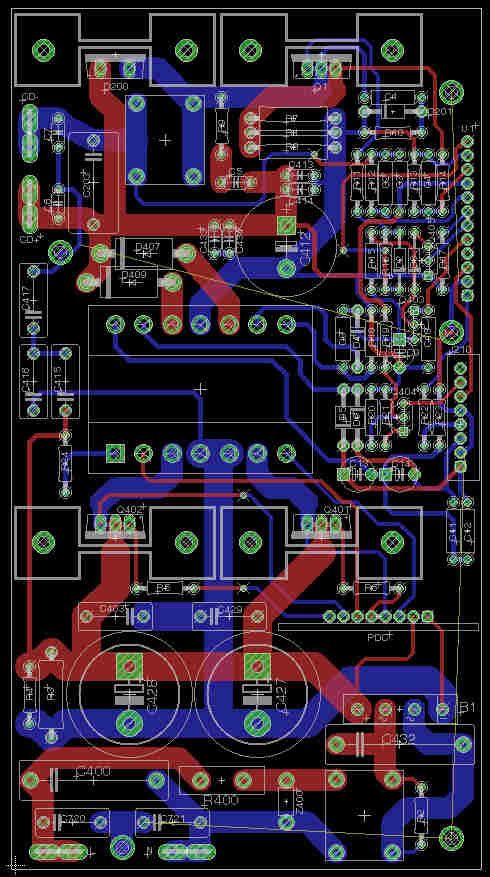
I have a very nice Klipsch Subwoofer that has failed due to poor design in the power supply. Origionally I was going to try and replace just the transformer but after fooling around with it I decided to reverse engineer and redo the whole power supply. Origionally the SMPS used what I believe to be an EER/ER35 Transformer with a vertical bobbin. I have found a good source of ETD supplies at mouser.com so I am planning on re-creating this using one of these cores. I understand that this is not going to be an easy task so I am just starting with the basics of creating the schematic and pcb's.
From what I gather BASH uses self-oscillating push-pull supplies in most of thier amps. Basically any BASH SMPS with a PDC board uses this mode of operation. I have 2 seperate amps/power supplies and they both use the same PDC control board. From this I believe that the ratio of the windings in the transformer are main operational factor.
I will do my best to make sure the schematics and pcb's are accurate as well as component values.
More to come!!!