mine xmps giving problem

ravs

Member
hi microsim,

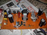
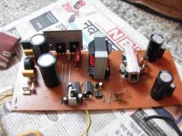
this is the smps iam trying to make.i tested things step by step.
first i checked for sgs352 it is working ok.pin no 14 and 11 were giving 5.35 and 5.40 volts
on supplying external 12 volt supply.then i inserted irs2110 pin no 1 and 7 were giving
different voltages pin1 5.40 volts and pin 7 giving 9.7 volts(floating) .and pin no 5 also giving 9.7 volts.i removed sgs3525 it didnt made any difference..then i connected irf450 .and transformer and powerd up with bulb in series.bulb glowed for less then a second
measured voltages across both mains cap to be equal.nothing was heating.voltages on
pin 1,7 of irs2110 were same but for pin 5 it was going out of range for my dvm.same
situation was on secondary side .then i connected a 100 watt bulb on secondary.
both bulb were glowing continuosly .voltage across the secondary was 70 volts dc.
i removed the series bulb and plugged it directly the fuse blow out.i thought since it
was i amp rated i replaced it with 3 amp this time fuse blows with hiss sound .blowing
mosfets and irs2110.

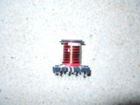
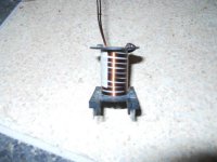
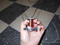
can you help me out in getting it to work.i wound 5 wires of 0.5mm wire
16 primary turns.and for secondary i used 4x 0.5mm wire 8 turns 4+4 wire in parellel
on etd 49.

ihave seen in invertors both the gate drive votages shoud be same in my case they
were not

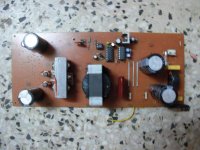
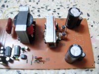
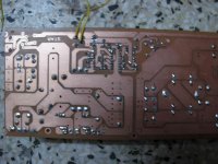
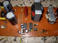
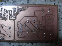
here are the schematic,pcb and transformer pics

thanks in advance

ravs

be a vegeterian.....
 

Attachments

  • 3.jpg
    3.jpg
    37.6 KB · Views: 41
  • DD48E108d01.pdf
    76.9 KB · Views: 70
  • 1.jpg
    1.jpg
    49.4 KB · Views: 41
  • DSCN0253.jpg
    DSCN0253.jpg
    61.1 KB · Views: 38
  • 2.jpg
    2.jpg
    65.8 KB · Views: 40
  • DSCN0256.jpg
    DSCN0256.jpg
    57.1 KB · Views: 41
  • DSCN0259.jpg
    DSCN0259.jpg
    60.5 KB · Views: 47
  • DSCN0265.jpg
    DSCN0265.jpg
    68.5 KB · Views: 41

MicrosiM

Administrator
Staff member
Smps

1. Hello Ravs


I am sorry cos you are facing problems, but lets try things.

If you don’t have an oscilloscope it will be a problem, and very difficult to diagnose.

1- What is your running frequency?
2- Core you are using? ETD49? Witch material?
3- Turns order of transformer?
4- Insulation between layers?


Cant see 6mm clearance between Primary and secondary on PCB

SMPS is very dangerous, so take care, I advice you to read:
http://www.diysmps.com/forums/showth...PS-development.


Lets start
 

ravs

Member
hi microsim,

i have already read these procedures.i have to start somewhere.while i switched it first time i was behind the door.

switching frequency is around 50 khz

f=1/ct(0.7rt from st datasheet
ct=1nf rt=15k

iam using etd 49 cf139 material cosmo ferrites here is the link
http://www.cosmoferrites.com/material_info.html

primary 16 turns 5 wires of 0.5mm wire .first 8 turns thick paper tape+pvc tape on top of that whole 8 turns for secondary 4+4 wire for each secondary 0.5mm x 4. 4 turns of 8 wires tape again 4 turns of 8 wires tape.wound parallel and split the ends in last.on top last 8 turns of primary.

gap between primary and secondary ground under the transformer is 3mm ill cut down the tracks to reduce the width if needed.

i asked ludo32 for his gate drive voltages his voltages seems to be equal.isnt it a problem for me.

thanks in advance

ravs

be a vegeterian.....
 

Attachments

  • under trans.jpg
    under trans.jpg
    51.6 KB · Views: 30

IGBT

Switching Fanatic!
Checks

I advice you starting with checking power supply, AUX, and make sure its working

REMOVE the feedback loop chip (opto coupler)

U need oscilliscope friend, I cant help any further into this without scope!

Check and tel me
 

ravs

Member
hi microsim and igbt,

cant afford a scope right now.

i removed the octocoupler and made measurements of input,output supply and on all pins of ic as well

aux input 15.50v
outut 11.97v through 7812

sgs3525 pin
1=nc
2=5.12v
3=11.8mv
4=nc
5=2v
6=3.76v
7=2.03v
8=4.86v
9=5.74v
10=26mv
11=5.40v
12=ground
13=11.97v
14=5.40v
15=11.97v
16=5.12v

ir2110
1=4.95v
2=g
3=11.97v
4=g
5=30.9mv
6=11.93v
7=4.78v
8=g
9=11.97v
10=5.40v
11=26.4mv
12=5.40v
13=g
14=26.4mv

and applying ac through a bulb

output on rectifier = 338v

1 probe on the common points of main cap and on positive=170v
1 probe on the commom point of main cap and other on ground=170v

voltage on gate of 1st mosfet 4.95 v
and that on second mosfet going out of range
also on pin 5 of 2110 that is connected to s,d of both mosfets gong out of range.
same on primary tapping connected to 2.2uf polyester cap.

and on secondary side even i connect only ground probe to ground it goes out of range.no voltages before or after rectifier.
core gets little warm.optocoupler is removed.

any thing else i could do.

thanks in advance

ravs

be a vegeterian......
 
Last edited:

ravs

Member
some videos as well

even single prob 15 watt load
[video=youtube;DqoOTt-kulE]http://www.youtube.com/watch?v=DqoOTt-kulE[/video]
output.flv


[video=youtube;LPgGO0j-wvk]http://www.youtube.com/watch?v=LPgGO0j-wvk [/video]

startup.flv
[video=youtube;hmJWP554g8I]http://www.youtube.com/watch?v=hmJWP554g8I[/video]

voltages on various points.flv (9.12M)

[video]http://www.metacafe.com/w/5852420[/video]


ravs

be a vegeterian.....
 

Attachments

  • DSCN0332.jpg
    DSCN0332.jpg
    87.9 KB · Views: 27
  • DSCN0331.jpg
    DSCN0331.jpg
    67.3 KB · Views: 18

MicrosiM

Administrator
Staff member
Smps

Ravs


Its impossible to know whats the problem,


I suggest you, that you biuld Ludo SMPS. its fully working and supported by diysmps


Thank You
 

ravs

Member
Ravs


Its impossible to know whats the problem,


I suggest you, that you biuld Ludo SMPS. its fully working and supported by diysmps


Thank You

hi microsim,

thanks for sugestion.i also think so will see it later.
but his pcbs are still not completed.its better in the mean
time ill try to manage money for components.

regards

ravs

be a vegeterian.....
 

Malmir

Member
Instead of cutting Your traces, then cut out or miller out the PCB material between the to traces so it can hold a small pcb, glue that small pcb into the slot. Many PCB materials has a breakthrough Voltage of 20-30 kV per mm in Z direction, this way You keep Your fat traces fat and gain an isolation.
 
Top