ultra
Member
Hi to everyone.
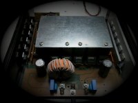
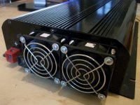
I will present a car amplifier that i designed two years ago.
Unfortunately for those who are interested in schematics, i will not post any as i try to make a living out of this.
So, please do not ask for schematics.
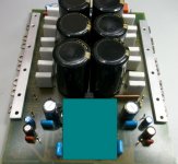
As in all car amplifiers there are 2 main stages, the step up smps, the audio amplifier.
As a housing i used an old heatsink from a DC to AC inverter.
The smps, the preamplifier, and all auxiliary circuitry are designed by me.
The power amplifier itself is an existing patented design, and i have written permission to use it from the patent .
I have only made some modifications to fit the application.View attachment 4055
View attachment 4057
SMPS
The main problem is to "pass the current" through the circuit.
Up to now, i have been using copper sheets cut on CNC machines to strengthen the underside of the pcb
View attachment 4058
this time i thought of something else, i used busbars that are already available to electricical shops
View attachment 4059
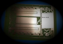
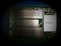
The prototype pcbs are shown below
i used photosensitive board, then liquid tin and finally i used a green coat spray
View attachment 4060
View attachment 4061
View attachment 4062
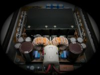
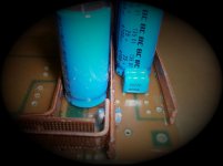
there is an input choke that along with large-high quality-electrolytic capacitors, forms a tuned circuit that stimulates 141,000μF at the 12V input.
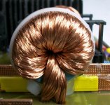
this choke is calculated for 150Arms
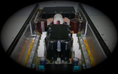
Now, the control pcb is a small board perpendicular to the main smps board and it is 100% made with smt components.
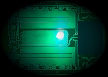
below you can see how the busbars are used in the pcb
I will present a car amplifier that i designed two years ago.
Unfortunately for those who are interested in schematics, i will not post any as i try to make a living out of this.
So, please do not ask for schematics.
As in all car amplifiers there are 2 main stages, the step up smps, the audio amplifier.
As a housing i used an old heatsink from a DC to AC inverter.
The smps, the preamplifier, and all auxiliary circuitry are designed by me.
The power amplifier itself is an existing patented design, and i have written permission to use it from the patent .
I have only made some modifications to fit the application.View attachment 4055

View attachment 4057
SMPS
The main problem is to "pass the current" through the circuit.
Up to now, i have been using copper sheets cut on CNC machines to strengthen the underside of the pcb
View attachment 4058
this time i thought of something else, i used busbars that are already available to electricical shops
View attachment 4059
The prototype pcbs are shown below
i used photosensitive board, then liquid tin and finally i used a green coat spray
View attachment 4060
View attachment 4061
View attachment 4062
there is an input choke that along with large-high quality-electrolytic capacitors, forms a tuned circuit that stimulates 141,000μF at the 12V input.

this choke is calculated for 150Arms
Now, the control pcb is a small board perpendicular to the main smps board and it is 100% made with smt components.
below you can see how the busbars are used in the pcb


