You are using an out of date browser. It may not display this or other websites correctly.
You should upgrade or use an alternative browser.
You should upgrade or use an alternative browser.
My first attend on building smps
- Thread starter nikoskir
- Start date
Hello Wally..
We have to points here...
1)keep the voltage regulated
2)keep the current at one point
so the first is already been accomplished by tl431 and optocoupler.
but this method is not good for current regulation..
we need an analog way.
so i am going a different approach..
by using pin 8 of sg3525..
it is better not to conflict both of them voltage and current regulation..
tonight i will put a comparator lm339 and do calculations....
and see the results.
i already put 2 resistors in both sides of dc 310...(i like things symmetrical ) 0.15ohm 5w.
my reference will come from low side it is about ~200 mv for 20 amps.
it is enough for a comparator to work....
if i finish it tonight i will post my results...
by the way with 2 trafo's at 7 volts each in series works much much better... !!!!!!!
thanks in advance
Niko
We have to points here...
1)keep the voltage regulated
2)keep the current at one point
so the first is already been accomplished by tl431 and optocoupler.
but this method is not good for current regulation..
we need an analog way.
so i am going a different approach..
by using pin 8 of sg3525..
it is better not to conflict both of them voltage and current regulation..
tonight i will put a comparator lm339 and do calculations....
and see the results.
i already put 2 resistors in both sides of dc 310...(i like things symmetrical
my reference will come from low side it is about ~200 mv for 20 amps.
it is enough for a comparator to work....
if i finish it tonight i will post my results...
by the way with 2 trafo's at 7 volts each in series works much much better... !!!!!!!
thanks in advance
Niko
Niko
“so i am going a different approach..
by using pin 8 of sg3525.."
Pin 8 of sg3525 = soft start. Are you sure that is the right pin?
“i already put 2 resistors in both sides of dc 310...(i like things symmetrical ) 0.15ohm 5w.
my reference will come from low side it is about ~200 mv for 20 amps.”
I assume you mean in the upper and lower leg of the half bridge. Make sure they are non inductive resistors also.
“by the way with 2 trafo's at 7 volts each in series works much much better... !!!!!!!”
Nice. Can not wait to see how you did it!
Wally
Niko
“so i am going a different approach..
by using pin 8 of sg3525.."
Pin 8 of sg3525 = soft start. Are you sure that is the right pin?
“i already put 2 resistors in both sides of dc 310...(i like things symmetrical ) 0.15ohm 5w.
my reference will come from low side it is about ~200 mv for 20 amps.”
I assume you mean in the upper and lower leg of the half bridge. Make sure they are non inductive resistors also.
“by the way with 2 trafo's at 7 volts each in series works much much better... !!!!!!!”
Nice. Can not wait to see how you did it!
Wally
Hello..
actually pin 8 as i test it with a pot 5v varying the voltage also varies the width of pulses..
you can go as low as it is not lowering the voltage of pulses..so it can be a way..
the other method is to use 2 comparators 1 for voltage and one for current and drive the error amp.....in analog way..
I'll do my tests and inform you..
yes the resistors are at the legs of half bridge in series with mosfets and and caps.
take care
Niko
Niko
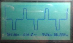
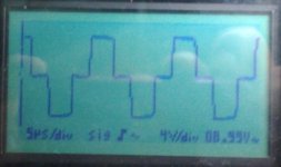
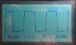
That was a very good idea to check the operation of pins 8 and 9 with a pot. Those waveforms look like you have a lot of control over the width of the waveform.
You probably know this, but just in case do not forget a RC filter after your current sense resistor to get rid of some of the switching noise.
Good luck
Wally
An update ..
I've managed to control current through pin 8.
Pin 9 is not possible because it cancels the error amp which we need for voltage regulation.
The voltage regulation we need only in small loads which make the voltage go up.
So every 10 amps of load i add.. i have 1 amp extra ...this means 10% accuracy till now.
The ac current of 230v stays steady ..... when i put more loads...
i suspect this comes.. because i use reference only from negative leg of half bridge..maybe i cannot tell..
i will make more rush the comparator and see results......
sorry for not posting any images or schematics.....i want to end tests first and then share all the info...
thanks
Niko
“The voltage regulation we need only in small loads which make the voltage go up.
So every 10 amps of load i add.. i have 1 amp extra ...this means 10% accuracy till now.
The ac current of 230v stays steady ..... when i put more loads...”
I do not understand what you are trying to say here.
Wally
So every 10 amps of load i add.. i have 1 amp extra ...this means 10% accuracy till now.
The ac current of 230v stays steady ..... when i put more loads...”
I do not understand what you are trying to say here.
Wally
As i read my post i cannot understand either 
I try better....
so i have 3 bulbs which draw 10 amps at 13v each one of them.
i connect one of them as load on smps.
the current is 10 amps....
i regulate the current through pin 8 and my comparator to 9 amps... which means voltage is falling...
then i connect one more bulb ..the current goes to 10 amps overall and the voltage goes more down...
and with all 3 bulbs connected i get 12-13 amps overall (otherwise it should be 30 amps and no voltage drop).
So till now the accuracy of current regulation is 10%...
even if i short circuit the output the current stays at 13 amps....no more....but the smps tends to switch off.
This is good for a hho cell to be stabilized....as i said when the temperature goes up the current draw by cell
goes really..high..
so the cell acts as current load..no matter the voltage is applied...means that if a cell draws 15 amps the voltage
would be 6-7-8-9 volts....it depends of the resistance of the mixture (water and kaoh) inside...
i hope it is more clear now....
Niko
OK, so you are saying it is working with 10% regulation and this is good for your application.
I spent several hours trying to figure out how to add current regulation and i did not figure anything out except that a sg3524 chip would be much easier.
Wally
no not 10% regulation......this is my error % on regulation.....
i will draw a schematic and you will try it......
using pin 8......
3524 is my thought also i'll try it next....
i will post also pictures of showing how it works....step by step...
actually in every 130 watts i have 100mv reference from the resistor...
so the skeptical is easy....if you find a way with comparator to alter the duty cycle and keep that reference steady
whatever load you put over 130 watts it will not raise the current......
Niko
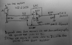
Here is a schematic of what i use for now....
please excuse my bad drawing...
the only thing you have to watch is that first let the smps
run with soft start and then attach the output of lm358 to pin 8.
I will also implement a delay to this circuit so it will let 3525 to soft start..
Niko
View attachment 4052
please excuse my bad drawing...
the only thing you have to watch is that first let the smps
run with soft start and then attach the output of lm358 to pin 8.
I will also implement a delay to this circuit so it will let 3525 to soft start..
Niko
View attachment 4052
So here is the double trafo...
each one is center tapped 2x7 volts 30A.
As you can see they are in series after the rectifying.
the windings are 20+20 primary 2+2 secondary.
Secondary is made of paralled 3 wires 2mm diameter each rail.
The primary have separate capacitor to float and the other endings
go straight to mosfets.
I had to take some turns out of primary to get the voltage .
.
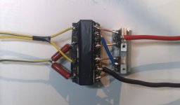
each one is center tapped 2x7 volts 30A.
As you can see they are in series after the rectifying.
the windings are 20+20 primary 2+2 secondary.
Secondary is made of paralled 3 wires 2mm diameter each rail.
The primary have separate capacitor to float and the other endings
go straight to mosfets.
I had to take some turns out of primary to get the voltage

Niko, very cleaver transformer setup, I see you made a module out of it. It is amazing how fast you put this smps together.
Were did you buy your transformer cores from.
Wally
Wally..
these 2 cores EL came from 2 atx supplies 600w by Thermaltake which i can buy for 5 euros each in road market..
this is the easy way for learning by doing before i start spending money in real projects......
they have enough space for winding.....and its dimensions are width the same as etd39 and height 7mm more.
i can disassemble them very easily...
i use hho gas with a very thin torch outlet around 1mm flame which has 800 Celsius temperature at tip...(i will post some pictures later)
and warming both sides of glue points very quick without the temperature go to all of trafo material..
As for fastness in smps design...well i have to tell you that if you want to make something work you have to read a lot in theory (which is 50% of knowledge)
and also read in real life what are people's results and failures and at last make your own tests.
Nothing is fixed...everything has to be tuned to work properly ......
i see this in my designs for low voltage high current pwm when i test with several new designed parts and these parts are behaving not as i expect...
Niko
p.s. did you have any test with the current regulation??
Niko, no i did not try the current regulation. I thought i would use an easier chip when i wanted to try it, like the sg3524 that has a pin for analog current limit. Or possibly the tl494 that can do foldback or pule by pulse current limit with some external circuitry.
I see you really get a lot of use out of your hho setup. I did not know you could make a torch.
http://www.instructables.com/id/DIY-HHO-Torch-Water-Torch-for-only-4/
Although this was a little scary.
"Safety Feature: The cling wrap serves as a safety cap. Most bubblers explodes when implosion occurs. This prevents this from exploding."
Wally
Hello Wally,
sorry for my delay in response i am on a business trip
so as for 3524 i already made a circuit and it works not as
i expected....the regulation can reach up to 80%
and that because the internal amp is not acting 100% as differential amplifier.
I will go on with it when i come back to base...
As for hho production 50% is the actual project and the other 50% is PROTECTION!!!
For indoor use i make gas separation cells meaning that oxygen and hydrogen are flowing
through different exits so there is no way for explosion....
if you are interested i can send you some very good info about my projects in pm.
this forum is for discussing SMPS projects ideas and it is not for hho production..
Take care
Niko

