n00b looking for some recommendations please?

JGalt

New member
Hello!

This forum is very exciting, I have always wanted to design an SMPS, but I never had a good reason to spend all the time and money needed to do it.

But now I have a great reason! I have a CNC mill which currently runs only at 7000 rpm. However, the manufacturer says if I can provide 190V at 12.5A, then I can run it at 10000 rpm, which is a very big deal in CNC machining!

So, there are so many choices with SMPS designs, I dont know where to start. I have looked at several hobbyist kilowatt SMPS designs, but none of them seem to be close enough to tweak.

I cant seem to find any multi-kw SMSP designs at this voltage (190VDC) from the major IC manufacturers. I.e. national webench poops outs well below my requirements.

I am an experienced EE but I have never done SMPS power supply design. But if I end up making something good here, I will definitely supply all my PCB layout, schematics, and BOM's so others could easily make it!

So my question is, could y'all recommend a particular topology or ballpark strategy to approach this? Or perhaps an existing design that is very close?

I am not in a rush and would like to enjoy this process.

So the specs are:

input: 110VAC @ 60Hz

output: 190VDC +/- 5V @ 12.5A (2375W)

thanks for any help!
 
Last edited:

MicrosiM

Administrator
Staff member
If that's not a regulated SMPS , then things would be easy.

If that's a regulated SMPS, then this will be a complex a little.

But I think you need a Full bridge SMPS controller, like UCC3895, or even you can use SG3525 in full bridge configuration, only thing I am worried about is the regulation issue.


Hope that helps
 

JGalt

New member
If that's not a regulated SMPS , then things would be easy.

If that's a regulated SMPS, then this will be a complex a little.

But I think you need a Full bridge SMPS controller, like UCC3895, or even you can use SG3525 in full bridge configuration, only thing I am worried about is the regulation issue.


Hope that helps

thank you for your help!

heres the thing:

this SMPS powers a motor controller which powers a BLDC motor. both the controller and the motor have a maximum voltage of 190VDC. So the voltage shouldnt go above that at any time.

And if the voltage falls below 180V then it wont get the motor up to 10000rpm.

So it needs to be between 180V and 190V.

I was thinking maybe if I can get the SMPS to always at least 195V, I can use a simple linear regulator to keep the output at 185V. At full current of 12.5A thats about 125W to dissipate in the linear regulator. Not pretty but doable and simple at least?
 

set111

New member
I would recommend just using a PFC circuit unless you need isolation.

They are fairly simple to build and can easily provide 190VDC +/- 5V if designed correctly.
As a heads up, one of the most critical parts is finding or building a suitable inductor and ensuring they wont overheat or saturate too much.

I have used the UCC28019 PFC controller before, the datasheet is very helpful and goes through all the calculations you need to work out the component values.
 
Last edited:

JGalt

New member
I would recommend just using a PFC circuit unless you need isolation.

They are fairly simple to build and can easily provide 190VDC +/- 5V if designed correctly.
As a heads up, one of the most critical parts is finding or building a suitable inductor and ensuring they wont overheat or saturate too much.

I have used the UCC28019 PFC controller before, the datasheet is very helpful and goes through all the calculations you need to work out the component values.

thank you for the recommendation

the UCC28019 datasheet and also the separate calculator are very detailed and useful. Unfortunately they are still just out of my reach to understand. I need to learn a little more before I get to that level, and then I am sure they will be very important in this project.

I have been looking online for designs of SMPS that are similar to what I need, here is what I have found:

Input VOutput VPowerOuput ITopologyLocationDescription
350122500208Full bridge173958.pdfDesign of a 2.5kW DC/DC Fullbridge Converter
60060150025Novel00701871.pdfDC/DC CONVERTER FOR HIGH INPUT VOLTAGE
600601500 Novel00867674.pdfFlying-Capacitor ZVS PWM 1.5 kW DC-to-DC
230 mains0-2301950 VariacGenRad_Experimenter_Oct_1955Brochure. Weighs 22lbs?
110 mains1417005DM2900?pst_psx.pdfunregulated linear power supply for servo amps..DM2900?
85 to 265 mains3903500.9PFC CCMucc28019.pdftexas instruments PFC CCM IC
     sluc069d.pdfvery detailed calculator for ucc28019 design
     ExcellentITvery detailed SMSP transformer design tool
110 or 240 mains1041000 ZCS resonanthttp://www.diysmps.com/forums/showthread.php?377-My-1KW-Commercial-SMPSMicrosim design diysmps
220 mains??1904500 ZCS series resonant http://www.diysmps.com/forums/showthread.php?381-My-2500Watts-to-5000Watts-Comercial-SMPS-for-Audio-AmplifiersDjLeco. No schematic. 200 to 300 euro. Pictures! ETD69, fixed freq


As you can see, the closest looks like DjLeco..unfortunately its commerical so no schematic is shared. But I am still looking. Hopefully I can find something close with a schematic.
 

KX36

New member
I take it it needs to be isolated from the mains, as is a safety requirement for most devices? 125W dissipation in the linear regulator's probably a bit too much and it could be more than this at times as the voltage or the current peaks or spikes. It's not that difficult to design a feedback loop for an off-line hard switching full bridge topology running on current mode control, adding isolation is a bit trickier. Ideally at this power level you'd use a quasi-resonant (ZVS/ZCS) topology but they're harder to design and have limitations on the minimum load current etc. High output voltage is a bit of a challenge because the secondary rectifiers won't be your standard schottkys, the output voltage stress can be minimised by having a high duty cycle around 0.8-0.9 which the full bridge converter allows, it should be doable in any case.

A PFC's main job is to shape the input current, the idea that its output voltage is relatively constant is a secondary concern. Different chips will control the output voltage in different ways, some will have the same output voltage independant of input voltage, some will follow the input voltage. Either way, they generally have a significant 100-120Hz ripple on them often designed around 10% of the DC output voltage (so 40V on a 400V boost PFC) as a biproduct of having a sinusiodal input current but a relatively constant output current. They're not the best things to use if you need tight output voltage regulation, unless of course you follow it with a second regulator, such as a bridge converter, as is usually the case.

I have to question the initial premise though; the manufacturer recommended you to run the motor at its absolute maximum voltage of 190V? Normally you'd have to leave a margin of error below this voltage for manufacturing tolerances. Or is 190V the maximum working voltage with a higher absolute maximum in the datasheet?
 

JGalt

New member
I take it it needs to be isolated from the mains, as is a safety requirement for most devices? 125W dissipation in the linear regulator's probably a bit too much and it could be more than this at times as the voltage or the current peaks or spikes. It's not that difficult to design a feedback loop for an off-line hard switching full bridge topology running on current mode control, adding isolation is a bit trickier. Ideally at this power level you'd use a quasi-resonant (ZVS/ZCS) topology but they're harder to design and have limitations on the minimum load current etc. High output voltage is a bit of a challenge because the secondary rectifiers won't be your standard schottkys, the output voltage stress can be minimised by having a high duty cycle around 0.8-0.9 which the full bridge converter allows, it should be doable in any case.

A PFC's main job is to shape the input current, the idea that its output voltage is relatively constant is a secondary concern. Different chips will control the output voltage in different ways, some will have the same output voltage independant of input voltage, some will follow the input voltage. Either way, they generally have a significant 100-120Hz ripple on them often designed around 10% of the DC output voltage (so 40V on a 400V boost PFC) as a biproduct of having a sinusiodal input current but a relatively constant output current. They're not the best things to use if you need tight output voltage regulation, unless of course you follow it with a second regulator, such as a bridge converter, as is usually the case.

I have to question the initial premise though; the manufacturer recommended you to run the motor at its absolute maximum voltage of 190V? Normally you'd have to leave a margin of error below this voltage for manufacturing tolerances. Or is 190V the maximum working voltage with a higher absolute maximum in the datasheet?

thank you for the detailed response KX36, its appreciated

I think we can thankfully ignore isolation because the machine already has an isolation transformer and we will be using the 110VAC output that transformer supplies. (it takes 220 vac single phase in and outputs 110VAC)

I have noticed that the ZVS/ZCS topology seems popular on this forum for high power. It also seems to have about 50% lower power dissipation according to poweresim.

The PFC is attractive to me because there are so many designs out there to look at and its also one of the more simple designs, the lack of regulation as you describe might be dealt with as follows, which also has to do with your question about 190V.

The spindle amp has a max input of 190V and the motor coincidentally has a max input of 190V. I'm not sure how hard both of those limits are, but yes, I'd rather stay below them as much as possible and still reach 10000 rpm. I listed 190V as the requirement for this to add a safety of margin in the opposite direction for this discussion..i.e. whatever comes out of this should be able to pump out 190V with no problem, even though really it should probably operate at 180V nominally, and I think 180V will get the motor to 10000rpm. Its a little unclear because I havent tested it and the motor is no longer documented at all from the factory. 180V is about right if you do the extrapolation from where it runs now, which is about 160V.

And then there is the bonus that 9500 rpm is really 95% as good as 10000rpm, so we probably dont really need to go all the way to 10000rpm, although it would be nice.

So there is some lee way here in our favor.

There appears to be PFC's with voltage feedback, yes? Cant I just use a regulated PFC? And isn't a "PFC" really just a boost converter that shapes its input current? So really we can just say "boost topology" and then add "with PFC to improve EMI and reduce input current peaks" and then add "regulated" to keep things at say 185V. Thats a common animal right?
 

MicrosiM

Administrator
Staff member
I would recommend just using a PFC circuit unless you need isolation.

They are fairly simple to build and can easily provide 190VDC +/- 5V if designed correctly.
As a heads up, one of the most critical parts is finding or building a suitable inductor and ensuring they wont overheat or saturate too much.

I have used the UCC28019 PFC controller before, the datasheet is very helpful and goes through all the calculations you need to work out the component values.


That sounds interesting to me, I am not sure how you can get 190VDC from the PFC output at any input voltage range from 85VAC ~ 264VAC, and did you try to load your PFC and then unload your PFC quickly? did you notice what will happen to the output voltage of your PFC?

I am still curios about the tests you have done.
 

JGalt

New member
That sounds interesting to me, I am not sure how you can get 190VDC from the PFC output at any input voltage range from 85VAC ~ 264VAC, and did you try to load your PFC and then unload your PFC quickly? did you notice what will happen to the output voltage of your PFC?

I am still curios about the tests you have done.

Fwiw the ucc28019 datasheet shows the 380vdc output of the evaluation module is stable within a couple volts across 85 to 264 vac across full current range of up to 1 amp..

Although thats quite different from the 190v situation since it would be below part of the mains input range
 

MicrosiM

Administrator
Staff member
Fwiw the ucc28019 datasheet shows the 380vdc output of the evaluation module is stable within a couple volts across 85 to 264 vac across full current range of up to 1 amp..

Although thats quite different from the 190v situation since it would be below part of the mains input range

That means we cannot get 190VDC from the PFC.
 

MicrosiM

Administrator
Staff member
I personally don't need to get 190vdc from 85 to 264, because the source I am using is 110vac always, I'm not sure why 85 to 264 got into the discussion


I dont mean any thing, Just was curious about how to get 190VDC from PFC, thats all.

No problems.
 

set111

New member
I assumed the input voltage was only 110VAC so it peaks at around 155V meaning a boost PFC can be used to produce 190V.

The output voltage of the PFC is set by a potential divider that goes into the VSENSE pin, I assume it would work correctly if set to around 190V.

As KX36 said the output would have 120Hz ripple, the peak to peak ripple voltage is given in the datasheet by Vripplepp = Iout/(2*pi*fmains*Cout) so if you wanted 10Vpp ripple you would need at least 3300uF of capacitance at the output.

The PFC I have built is a 230V input, 400V output at around 3KW for a bench power supply I am currently building, I will post a thread containing all the info when it is finished. I have tested the PFC up to 2.4KW so far and everything apart from the load remained cool, I got some nice ~6A 2" arcs off that thing :)
 

MicrosiM

Administrator
Staff member
I assumed the input voltage was only 110VAC so it peaks at around 155V meaning a boost PFC can be used to produce 190V.

The output voltage of the PFC is set by a potential divider that goes into the VSENSE pin, I assume it would work correctly if set to around 190V.

As KX36 said the output would have 120Hz ripple, the peak to peak ripple voltage is given in the datasheet by Vripplepp = Iout/(2*pi*fmains*Cout) so if you wanted 10Vpp ripple you would need at least 3300uF of capacitance at the output.

The PFC I have built is a 230V input, 400V output at around 3KW for a bench power supply I am currently building, I will post a thread containing all the info when it is finished. I have tested the PFC up to 2.4KW so far and everything apart from the load remained cool, I got some nice ~6A 2" arcs off that thing :)


Very interesting, did you face any issues or problems when stepping the load?

Also I dont think its possible to tune your PFC to 190VDC.
 
Last edited:

set111

New member
Very interesting, did you face any issues or problems when stepping the load?

Also I don't think its possible to tune your PFC to 190VDC.

I had no major problems with my PFC partly because I have over-engineered it a bit and done my research.

This software was very helpful when making the inductor. http://www.micrometals.com/software_index.html

My PFC definitely wont be able to produce 190VDC without serious modifications and a lower input voltage.
 

KX36

New member
PFCs are interesting. Reducing the output voltage ripple can increase the input distortion, and it's the (relatively) low distortion sinusoidal input current that's usually the main goal. Because this ripple is part of the design, it's a requirement that the voltage feedback closed loop bandwidth be low, typically around 20Hz. Much higher bandwidth and it will try to get rid of the ripple at the expense of worse input current distortion. The low bandwidth gives it a long time constant and so they have a very poor step response with generally a significant overvoltage transient on startup. I still don't think a PFC is right for this application, at least not alone.

However, if the output voltage requirement is always greater than the input voltage, that doesn't mean a boost converter's out of the question. If you forget trying to shape the input current, you can get a well regulated, low ripple output with a much better step response and less chance of overvoltage peaking, although you'll probably still need overvoltage protection. The design is simpler than a PFC, with no input current sensing and shaping to worry about and with no isolation, compensating an error amplifier is easy. Boost converter's switch is on the low side, so you don't have to worry about high side driving (gate drive transformers etc) and you can still implement current mode control (CMC), which you most likely should do. It will likely be a continuous conduction mode (CCM) converter at that power level. You still have to take care of the right hand plane zero, which limits bandwidth, but its easy to get the formula for that and set the bandwidth below 1/3 of the RHPZ frequency.

Some reference reading:
Under the Hood of a DC/DC Boost Converter - Brian T. Lynch
Your converter would probably look something like that in Fig 1, perhaps with the addition of a low voltage flyback winding on the inductor for the IC's Vdd pin, like in (b) in the image below, as a resistive drop from a high voltage input to a low voltage converter pin can be quite inefficient (although at the power level you're talking, the power lost in a simple dropper's probably insignificant anyway).


A SiC schottky diode may be a good choice for the boost converter diode. They can be quite expensive but they should work well and they're easily implemented. At high voltage you don't have many options. In CCM you need a very fast recovery diode (like Schottky fast, almost instant) and it would probably be the same story for the rectifier diodes whatever topology you used. Here's what looks like a reasonable example based on a 2 minute search
Infineon IDH16G65C5XKSA1 650V 16A SiC Schottky in stock at Mouser - £7.42 in single quantities. EDIT: Actually come to think of it, the current rating of that one might not be sufficient as the peak currents will probably be higher, I foolishly spec'd it on the average current since I didn't spend the time to think about it.

P.S. Your mains frequency isolation transformer must be a beast to handle that much power. I take it its a site transformer. I like them; high power, easily available and relatively cheap. IIRC, A lot of professional power tools only come in 110Vac input so most tradesmen have them in the UK. :)
 
Last edited:

JGalt

New member
PFCs are interesting. Reducing the output voltage ripple can increase the input distortion, and it's the (relatively) low distortion sinusoidal input current that's usually the main goal. Because this ripple is part of the design, it's a requirement that the voltage feedback closed loop bandwidth be low, typically around 20Hz. Much higher bandwidth and it will try to get rid of the ripple at the expense of worse input current distortion. The low bandwidth gives it a long time constant and so they have a very poor step response with generally a significant overvoltage transient on startup. I still don't think a PFC is right for this application, at least not alone.

However, if the output voltage requirement is always greater than the input voltage, that doesn't mean a boost converter's out of the question. If you forget trying to shape the input current, you can get a well regulated, low ripple output with a much better step response and less chance of overvoltage peaking, although you'll probably still need overvoltage protection. The design is simpler than a PFC, with no input current sensing and shaping to worry about and with no isolation, compensating an error amplifier is easy. Boost converter's switch is on the low side, so you don't have to worry about high side driving (gate drive transformers etc) and you can still implement current mode control (CMC), which you most likely should do. It will likely be a continuous conduction mode (CCM) converter at that power level. You still have to take care of the right hand plane zero, which limits bandwidth, but its easy to get the formula for that and set the bandwidth below 1/3 of the RHPZ frequency.

Some reference reading:
Under the Hood of a DC/DC Boost Converter - Brian T. Lynch
Your converter would probably look something like that in Fig 1, perhaps with the addition of a low voltage flyback winding on the inductor for the IC's Vdd pin, like in (b) in the image below, as a resistive drop from a high voltage input to a low voltage converter pin can be quite inefficient (although at the power level you're talking, the power lost in a simple dropper's probably insignificant anyway).


A SiC schottky diode may be a good choice for the boost converter diode. They can be quite expensive but they should work well and they're easily implemented. At high voltage you don't have many options. In CCM you need a very fast recovery diode (like Schottky fast, almost instant) and it would probably be the same story for the rectifier diodes whatever topology you used. Here's what looks like a reasonable example based on a 2 minute search
Infineon IDH16G65C5XKSA1 650V 16A SiC Schottky in stock at Mouser - £7.42 in single quantities. It should dissipate around 18W while conducting, but it only conducts for part of the duty cycle and that's still a small fraction of your total output power.

P.S. Your mains frequency isolation transformer must be a beast to handle that much power. I take it its a site transformer. I like them; high power, easily available and relatively cheap. IIRC, A lot of professional power tools only come in 110Vac input so most tradesmen have them in the UK. :)

Very interesting!

Yes as a sort of gut check, if this isnt what boost converters are for (110VAC to 190VDC), than what good are they right?

I am fine with abandoning the PFC aspect, although I don't really know what the consequences of that might be beyond what you laid out. So it will be a bit of blind assumption on my part.

As far as compensating the feedback loop, I have a general understanding, but I'm not sure how much of that is simply designing the feedback network correctly, and how much of it is designing the whole converter correctly (including expected performance) so that it can actually be stable and tuned properly. What do you think?

Im definitely going to dive into that Lynch paper, looks juicy.

Is the Vdd resistor you mentioned for bootstrapping the controller IC? I think I may have several low voltage rails I can use for that since this converter will literally only power the mill spindle motor and the rest of mill control electronics will be alive at all times.

The isolation transformer is in a metal box about 12" x 12" by 7". I think it weighs about 20 lbs. It must be rated for more like 4kw because the mill is rated 2hp spindle and it also has 3 axis motors which operate simultaneously, and at least a few hundreds watts of electronics to power. I think its just an EI style too, definitely not a toroid. Does that seem weird?

So its really starting to seem like a boost converter can handle this and wouldn't be reinventing the wheel.

Now the challenge is to start coming up with an actual design and some component part numbers.

Have you used poweresim.com? What do you think of it? It seems like a good place to start. That or the UCC28019 spreadsheet calculator.
 

KX36

New member
Actually, forget the panic edit I just made about the schottky's current rating, its generally OK to spec a schottky boost diode based on the average output current as they are capable of much higher peak currents, so even as the current momentarily passes the max continuous current, the diode should still survive.

Some more recommended reading:
Basic Calculation of a Boost Converter's Power Stage

Abandoning the PFC aspect will mean it draws current from the mains in 120Hz spikes, rather than smoothly, like a linear power supply or indeed a SMPS without PFC would. There will be more EMI etc. but hopefully not a problem.

Design the power stage of the converter correctly, with the right inductor and capacitor, continuous conduction and preferably current mode control and I can help you to compensate it. The link I've just given I skimmed through and it should guide you right through it. It shouldn't take me more than 5 mins to get a stable compensator. Just remember to design for the full range of input voltage etc (what's high and low for your country and how much will you let the rectified input voltage sag between 120Hz charging pulses, you don't want it to stop working if you move house etc.)

The Vdd thingy's just to power the IC, so if you have an available appropriate power rail already, even better.

Laminated steel EI power transformers are cheap and common at mains frequency. Torroids have lower flux leakage but winding a toroid commercially is expensive. Most site transformers are an EI transformer in a bucket. As you see, the weight is the main issue, but in the case of an isolation transformer it doesn't really affect the salability of the product.

I havent used PowereSIM. I do heavily use computer simulations though. SPICE and SIMPLIS. The best place to start is on paper using the known equations for a given topology; D=(Vout-Vin)/Vout and Vout/Vin=1/(1-D) for boost converters, di/dt=V/L in inductors, dv/dt=I/C in capacitors, etc. then try to get it working in a sim.
 
Last edited:

JGalt

New member
Actually, forget the panic edit I just made about the schottky's current rating, its generally OK to spec a schottky boost diode based on the average output current as they are capable of much higher peak currents, so even as the current momentarily passes the max continuous current, the diode should still survive.

Some more recommended reading:
Basic Calculation of a Boost Converter's Power Stage

Abandoning the PFC aspect will mean it draws current from the mains in 120Hz spikes, rather than smoothly, like a linear power supply or indeed a SMPS without PFC would. There will be more EMI etc. but hopefully not a problem.

Design the power stage of the converter correctly, with the right inductor and capacitor, continuous conduction and preferably current mode control and I can help you to compensate it. The link I've just given I skimmed through and it should guide you right through it. It shouldn't take me more than 5 mins to get a stable compensator. Just remember to design for the full range of input voltage etc (what's high and low for your country and how much will you let the rectified input voltage sag between 120Hz charging pulses, you don't want it to stop working if you move house etc.)

The Vdd thingy's just to power the IC, so if you have an available appropriate power rail already, even better.

Laminated steel EI power transformers are cheap and common at mains frequency. Torroids have lower flux leakage but winding a toroid commercially is expensive. Most site transformers are an EI transformer in a bucket. As you see, the weight is the main issue, but in the case of an isolation transformer it doesn't really affect the salability of the product.

I havent used PowereSIM. I do heavily use computer simulations though. SPICE and SIMPLIS. The best place to start is on paper using the known equations for a given topology; D=(Vout-Vin)/Vout and Vout/Vin=1/(1-D) for boost converters, di/dt=V/L in inductors, dv/dt=I/C in capacitors, etc. then try to get it working in a sim.

this is great! i'm taking all your advice and proceeding down this road.
 

JGalt

New member
this is great! i'm taking all your advice and proceeding down this road.

Okay since I am a beginner in SMPS i'm trying to get my brain in "smps mode".

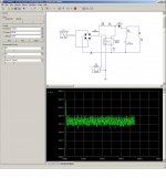
I have an urge to draw up a converter that will be as similar as possible to the boost converter I actually need to make, in SPICE (Circuitmaker 2000, my fav from olden times)

I.e. something like a 110VAC to 190VDC at only 1A, but same topology i.e. boost, CCM with current mode control.

So according to KX36 equations:

Duty cycle = (190-155) / 190 = 18%?

I have alot of reading to do.

I'd like to build up a proper SPICE SMPS using only information I actually understand (no guessing or blind copying) as a self teaching method.

So hopefully with all the app notes, white papers, datasheets, and forum help, I can slowly but surely select the SMPS components and define the parasitics properly in spice. I'll make the controller circuit out of discrete blocks in spice because it doesnt have any SMPS IC models.

Some main components to figure out first:

-freewheel diode
-output capacitor
-mosfet/igbt
-main inductor
-fullbridge diode and accurate mains rectifier parasitic modelling
-simple control logic to get to 190VDC at 1A unregulated for learning?


spice begin.JPG
 
Top