twenglish1
New member
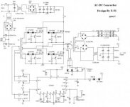
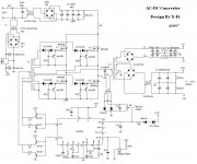
Hello everyone, i am starting a project to build a high power switchmode supply that will act as the power source for a homemade plasma cutter, i don't want to hear start with something easier and lower power since i am new to this, i have made the decision that the best way to learn is to just jump right in and just do it, i also understand all the necessary safety precautions. This power supply i plan to build will have 330v open circuit voltage and need to be limited at 40 amps short circuit current. I am still in the research and design phase. I have decided to use a half bridge inverter design, and i will be driving it with an IR2153. So far i have purchased a lot of EE80 ferrite cores, the mains rectifiers, large filter capacitors, the IR2153 chips, and a lot of large 1200v, 150amp IGBT half bridge modules, i will post my schematic shortly for all to see. i dont have any specific questions as of now, just posting to see if anyone has any input or pointers that could help me along with this project