Repair of smps SOUNDCRAFT PSM300 HELP needed

Resonant

New member
Hi, first post here.

I've always admired switch mode power supply's and have always wanted to make one, since I already have a nice small class T amp to go with it, but never had the time and money to invest much.

So when a friend of mine came along with a soundcraft power supply that needed repair I said "sure! I'll take a look at that, no problem.." since it would be a nice learning opportunity
Well..ends up I'm in over my head. Darn thing just wont work.

After fixing a few problems and blowing some mosfets I've spent hours on the net looking for solutions until I found this site witch has been delightful to read.

But anyway..still couldn't figure out my problem..


Is anyone here willing to help a noob in smps??
I have schematics, multimeter with inductance measuring, digital scope and can take pictures
 

MicrosiM

Administrator
Staff member
Kindly post some pictures, I can help you out


And show some close pictures of the PCB of the power supply, and try to mention parts names

regards
 

Resonant

New member
power supply gives out +17v -17v and +48v

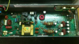
smps1.jpg

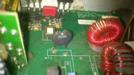
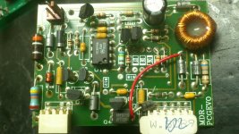
first thing I noticed when it arrived is that the surge resistor was blown, so I shunted it out with a thin wire since every shop I went to told that they don´t have them in stock and it would take weeks to get.

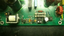
smps2.jpg

this is a section of the power supply thats called an auto-ranger, for working with 120v or 230v. It didn't seem to be working properly (50Hz vibration) so I disconnected it to work only in 230V mode.
Is it really necessary to be able to work with 120V?? since it only shunts one of the capacitors to the neutral I cannot see the point of it.

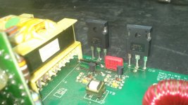
smps3.jpg

These are the power mosfets(IRFP450) that power the transformer and were shorting out. I replaced them only to blow out the replacements in less then a second. So went out to get more but this time they didn't burn straight away (by this time I had disconnected the auto-ranger, not sure if it was this that helped)

smps4.jpg

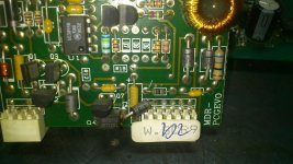
As I was taking the photos I noticed this cut in the copper trace. It was like that when it arrived

smps5.jpg

So hoping this would resolve the problem of not working I closed the circuit with a peace of wire. Didn't work...

smps6.jpg

I will have some screen shots of the scope as soon as I can so you can have an idea of what it doing

thanks for taking the time
 

MicrosiM

Administrator
Staff member
Hi resonant,

best thing to start with, Connect Lamp in series with the 220VAC line while you are doing the below

1- You have to make sure that the AUX (Standby power supply) is working or NOT. disconnect the driver board. It looks to me that Q1 and Q6 is that circuit that you have to check.
UCC3844 power supply pins is 5 for GND, and 7 for VCC, follow these and make sure there is voltage when you connect the power supply to the 220VAC line.

once you confirm that there is power at those pins, we can move forward.


please remove those IGBTs from the PCB, replace ALL damaged parts ( the ones you have tested)


regards
 

Resonant

New member
I took some screen shots of the oscilloscope but there seems to be some problem uploading them.

Mosfets where removed and Lamp was connected in series.

Power to pins 5 and 7 on UC3844 is failing, its triangular on the scope.
As output pin 6 activates there is a sudden power drain witch lowers VCC on pin 7 and output stops, voltage slowly rises to the point where output is again activated and VCC is drained again.
All happens within about a 7Hz cycle.

The output signal from pin 6 is 122kHz and seems to reach the mosfets nicely.

I'll try and upload photos again soon.. its much better then me trying to describe them :p
 

MicrosiM

Administrator
Staff member
Thanks Wally an Resonant


I am working around the clock to make the new board up and runnig.

If you notice any problem please post in the forum problems

Now it should be fine

Thanks Again :UP:
 

Attachments

  • smps.jpg
    smps.jpg
    58.4 KB · Views: 46

Resonant

New member
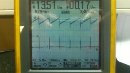
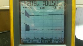
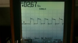
This is a shot from the UC3844 chip
channel A being Vcc and channel B is measured at output pin 6

uc3844 voltage and output.JPG

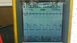
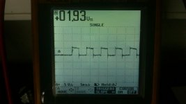
Next two shots are zoomed in
please note time scale

voltage and output zoom.JPG
voltage and output zoom2.JPG

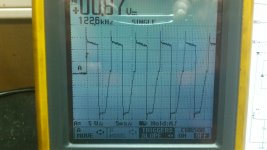
this is the signal as it leaves the board and heads to the isolating transformer towards the mosfets

signal to isolating transformer.JPG

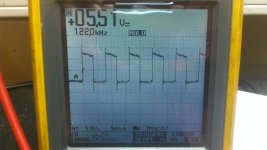
and here is measured at the gate of the mosfets
mosfet drive signal.JPG

sorry for being phone pictures but I've misplaced the oscilloscope cable to connect it to my PC.

thanks
 

MicrosiM

Administrator
Staff member
Ok

I want you to check and to confirm if the waves across G+S of each Mosfet is good, PLEASE POST them also.

Please check with DMM voltage across the UCC chip, and confirm if its correct or not.
 

Resonant

New member
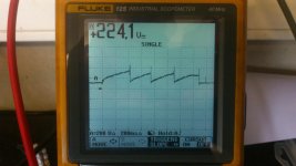
That information is correct. voltage across chip is saw tooth in shape.
max volt 16V
min volt 10V
average volt 13,4V
 

MicrosiM

Administrator
Staff member
That information is correct. voltage across chip is saw tooth in shape.
max volt 16V
min volt 10V
average volt 13,4V

It seems that the UCC3844 chip is working, and the AUX supply feeding it is working.

Let me know Mosfets you are using (Part Number)
 

Resonant

New member
Original Mosfets where IRFP450.

I've already burnt two pairs of mosfets.

And right now I have two IRFP450A waiting to go in but they will also burn unless I find out the problem.

I don't know much about smps transformers but it doesn't seem burnt or shorted out.

Are you sure voltage across chip is supposed to be like that?
 

MicrosiM

Administrator
Staff member
Original Mosfets where IRFP450.

I've already burnt two pairs of mosfets.

And right now I have two IRFP450A waiting to go in but they will also burn unless I find out the problem.

I don't know much about smps transformers but it doesn't seem burnt or shorted out.

Are you sure voltage across chip is supposed to be like that?


Yes, voltage looks OK, also waves and frequency.

I want you to put two resistors between G+S of EACH mosfet, and show me waves with the resistors connected, each resistor value 47R.

If you have good waves, then try 22R and tell me result

Do this test without mosfets on PCB


Regards
 
Last edited:

MicrosiM

Administrator
Staff member
Looks good

Now you have to make a test, If you have Variace I advice that you use it, or 110V source, if not the chance to damage the mosfets is 50%, if you accept that do it, or dont.

KEEP THE LAMP CONNECTED (100W BULB)

and solder the Mosfets on the PCB, connect the driver boards

no need for heat sink at this stage, connect the SMPS to the 110V or 220V for 1 second, and see if the lamp light, let me know result

I think that you may have a problem at the output stage, please try to inspect the PCB before powering up
 

Resonant

New member
Looks like your on to something

Lamp would light up brightly a few times per second.

Voltage across main capacitors was drained severely at each pulse
cap volt.jpg

I cannot see any obvious signs of problems on the output stage but I'll keep looking
 

Resonant

New member
Found it!!

Diode on the 48V side was shorting out.
Both +17V and -17V are running

Of to the shop to get new diode and soldering iron since mine just decided to stop working to.

You are the man! I would get you so drunk if you were here right now

Thank you :w)
 
Top