Hi i'm a Tom and it's my first topic,
I have problem with output power in my smps. In assumptions i wanted to get output voltage from 10V to 35V with regulated current from 1A to 15A.
Topology: Half Bridge
Core: ETD44 3C90
Frequency: 50kHz
Input Voltage: 320V
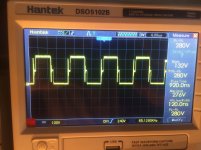
Windings calculated in ExcellentIT( ) but the lice I wound manually, wrongly cut the wire length and ran one turn at the primary winding and the secondary in relation to ExcellentIT. In the diagram that I posted red crosses, I marked the elements that were not soldered. The only difference with the schematic is the RC snubbers in parallel with the transistors. (Drain, Source) 2.7nF capacitor and 10 ohm resistor. Without them there were significant oscillations on the transistor drain, which, when powered by 320V, caused them to break. When the snubbers are used, the keys work fine, but the power dissipated on the resistors is so large that the inverter can operate for a maximum of 20 seconds and then the resistor is going to smoke.At the moment, the SG3525 works without feedback. The error amplifier on + has 3.6V on - it is 0V. Outputs PWM A and B work around 50%. During the test with a light bulb, the car 55W 12V light dim. The current is about 3.3A while the voltage as well I remember about 6V.I will add that the SG3525 is powered by an isolated 15V power supply
Please tell me why the output gets so little current? Why does the voltage so drop? Without load I have about 39V.


Schematic ->View attachment Schematic Prints.pdf
I have problem with output power in my smps. In assumptions i wanted to get output voltage from 10V to 35V with regulated current from 1A to 15A.
Topology: Half Bridge
Core: ETD44 3C90
Frequency: 50kHz
Input Voltage: 320V
Windings calculated in ExcellentIT(
) but the lice I wound manually, wrongly cut the wire length and ran one turn at the primary winding and the secondary in relation to ExcellentIT. In the diagram that I posted red crosses, I marked the elements that were not soldered. The only difference with the schematic is the RC snubbers in parallel with the transistors. (Drain, Source) 2.7nF capacitor and 10 ohm resistor. Without them there were significant oscillations on the transistor drain, which, when powered by 320V, caused them to break. When the snubbers are used, the keys work fine, but the power dissipated on the resistors is so large that the inverter can operate for a maximum of 20 seconds and then the resistor is going to smoke.At the moment, the SG3525 works without feedback. The error amplifier on + has 3.6V on - it is 0V. Outputs PWM A and B work around 50%. During the test with a light bulb, the car 55W 12V light dim. The current is about 3.3A while the voltage as well I remember about 6V.I will add that the SG3525 is powered by an isolated 15V power supplyPlease tell me why the output gets so little current? Why does the voltage so drop? Without load I have about 39V.
Schematic ->View attachment Schematic Prints.pdf