Some questions about my SMPS TIG Welder build...

blasphemy000

New member
Very cool. Thanks for the link KX36. Was really cool to see inside a high-power production unit like that just to see a little bit of how they designed it.
 

Cioringa

New member
hello, here is a project from rusia i think the only TIG AC-DC built from scratch http://samopal.su/node/24 you can use google translate ...

i am also working on converting a Lincoln TIG into a AC unit, Lm555+lm339 for generator square wave and duty cycle plus HCL3120 opto drivers and TC4452 current boost ... for ibgt i`m thinking of using GA300TD60S modules altough they are quite expensive compared to discrete solutions like irg4pc50s...
 

kees54

kees57
Hi There all.


I have an idea to make my MIG welder who was 3 fase and has a burn transformer.

However the schematics I can find are al of the constant current source type, and I need for MIG a constant voltage source.

Now this looks as a normal 22 volt supply who keeps voltage constant until the current protection trips.

Are there some people here prepaired to help me out, I have some schematics who have open outputs, I see much LM series analog ic,s
used before the UC3845 or the SG3525 for example a inverter who can be switched between CC or CV, I also need with a CV
put capacitors on the weld output to make clean dc. The LM analog ic,s are for make dc fluctuation minimal by more adjustement room?
one schematic even did use a OP07 opamp before the voltage feedback input.

My idea was keep the current feedback in primairy and adjust on max amps as a protection against overload, eventual adjustable.
Inplement a voltage feedback loop from weld output pins (before or after output shoke?) and put elco,s on the output to make
cleac DC.

And I can weld MIG.Mag.

Also, I can switch this way also between CC and CV with some relais? who switch elco,s of and voltage feedback so I can use current feedback alone
as intended.

see picture.

I need not very big KW, 140 amps are more then enough, I have a E71/33/32 C390 AL10800 core.


Thanks very much for the help.

PS I am a audio amp designer, I do hybrides (tube/mosfet), I see this smps are very interesting for it.
 

Attachments

  • shema.gif
    shema.gif
    113.5 KB · Views: 258
Last edited:

kees54

kees57
I am busy now with a welder, ****** was hospitalized so not much time, but is better now,

I think about use a series resonant type of welder smps, I do not need more then 150 amps for mig mag
It is a full bridge version and I do use a capacitors Cs some paralelled in series with output trafo so it never can
saturate, for welders this is used often I did see on expense welders and cheap ones, paralleling some polyester
caps and a series resonant like in the schematic.

How did end this project? because there is never be people active here sinds 2014.

I do still need what is de best way to make voltage source and not current source, I did see some schematics
there is output capacitors used for the mig mag version with voltage feedback, I can use even double one
with relais who disconnect capacitors on output in tig mode setting voltage max and current on what
is needed.

Tips are welcome also.

ScreenHunter_514 Apr. 17 13.51.jpg

thanks.

kees
 
Last edited:

blasphemy000

New member
Not much really happened with this project due to real-life getting in the way. I haven't had much time to work on it.

I did build up a simple TNY27* based fly-back auxiliary power supply(It's posted on this site somewhere) as a proof of concept to power all the control circuitry. I ended up using that Aux board as a low-power bench supply as it didn't make enough power to drive all of the switching devices that would have been needed for the welder.

I have some Alpha versions of schematics I've drawn up of the control circuitry(they're buried somewhere on this computer) as far as controlling the output current and current pulsing features(pulses per second, main current, background current, on-time/duty-cycle). I've also got some schematics for controlling the output chopper stage to give a square-wave output current for TIG welding in AC. The chopper has variable frequency(20-250Hz), AC balance control, and the chopper's H-Bridge also doubles as a way to electronically switch the output polarity(just leaves one half of the H-Bridge constantly powered depending on the output polarity desired). The current pulsing feature works when the output is set to AC but due to the nature of unbalanced AC TIG welding, the best performance would come with a pulse frequency either way faster, or way slower, than the AC Output frequency. I've never actually had a need to use automatic pulsing when welding aluminum(I've always just manually pulsed the current with the foot-pedal when required), so the final circuit I designed provided an alternative use for the current pulsing feature when the output was in AC mode. What this circuit does is when the welder's output was set in AC mode, it uses the PWM signal that comes from the output's AC Balance controler to also drive the current pulsing circuit. This effectively gives you a way to control the output current of the negative half-cycle(main current on the pulse) of the output square-wave separately from the positive half-cycle(background current on the pulse). I've seen this feature on some of the much more advanced digital TIG welders that you see sold on the market these days. It basically allows you to have the full amount of output current when the AC output is in the negative swing, providing normal penetration of the weld pool. When the output swings positive though, the pulse controller switches to "background current" and that current is used for the positive half-cycle of the output. When TIG welding really clean aluminum on AC with a square-wave inverter machine, you can usually set the AC balance to 75-90% negative balance with no ill effects on the weld quality, deeper penetration, and it allows the use of a semi-sharpened electrode to provide better control over the arc. The problem arises when you run into aluminum that is "less than ideal" for welding. To make it easier to weld, and burn/blast out the contaminants/oxidants, you turn the balance down to between 50-65% negative balance. This provides more cleaning action when the output is in the positive half-cycle and makes for a cleaner weld. The problem, or annoyance, becomes that with more time spent in the positive cycle, this will melt back your electrode into a rounded or balled tip just like you would have to weld with on an old transformer machine that has no balance control at all. Being able to limit the current only in the positive cycle can help minimize this electrode melting effect while still giving more time for the cleaning action to take place with the lower setting on the balance control. Alternatively it can be used to assist you when welding very thin aluminum parts while minimizing burn through. This can be achieved by turning the balance control to be mostly positive(<50% to reduce penetration) then also setting the positive half-cycle current fairly low(allows for a sharpened electrode for more precise arc control). All of my control circuitry is entirely analog, fairly straight forward and simple. There are a couple of CMOS logic gates between the chopper controller and the driver boards for the massive(2x400A) output dual-IGBT bricks just as a double safety feature to help ensure there is no shoot-through in the output stage as that would be VERY catastrophic. I also had a simple circuit that limited the Open-Circuit Voltage when the welder was in SMAW(Stick) mode to reduce the risk of electrocution while inserting a new rod into the holder.

Unfortunately despite my incredible ambitions, this project is currently on indefinite standby. I have recently been occasionally messing around with the controller simulations and tweaking stuff here and there to simplify the design and make routing the controller boards easier if I ever get that far. I've also been working on some digital, microcontroller powered, circuitry, but only to provide digital readouts of voltage and current so far. Despite being a great programmer on a PC using various OSes and Programming Languages, I'm very new to microcontrollers. I'm sure if I had the time I could convert the whole setup to use a microcontroller that handled all of the logic and had control over the analog control loop for the switching stages. Before I quit actively pursuing this project I had settled on the final design consisting of a multi-phase PFC/Boost input stage(400VDC output), followed by either 3x100A hard-switched full-bridge switching stages, or 6x50A stages, paralleled together to provide the 300A output current. I was about to start ordering the parts to build up one of each of the switching stages(100A and 50A) to see which would be more reliable, more size friendly, and cheapest route, once all the stages were combined, but alas, life got in the way and that's where this project ended.

As far as building a MIG/MAG welder using a SMPS to provide the output power. I've honestly got no idea. I've never had the pleasure of digging into one of those types of MIG welding machines and like you, I've had a hard time coming across schematics for such a machine online. I did recently take apart a small 120VAC, mains-transformer based MIG welder. It only had four voltage settings which were selected via a multi-tapped primary on the transformer to provide the different winding ratios. The secondary was a full-wave center-tapped design with the output voltage being filtered via a large inductor and a 50,000uF/36V capacitor to keep the output voltage stable for the MIG process. Maximum output was only rated at 90A @ 20% duty-cycle as it was a fairly small welder. The 24VDC electric motor that provided the wire feeding developed some sort of intermittent short that would randomly blow the fuse. For years I just had the fuse wrapped with aluminum foil and never had an issue out of it until the motor completely shorted out and blew the small diode bridge that provided the drive power for the feed motor. The bridge could have been easily replaced with parts from my junk bin but I was unable to find a suitable replacement for the motor and the motor itself was sealed and I was unable to get it apart. I did reuse most of the welder. I removed the massive output capacitor from the circuit(I retained the inductor though, effectively providing a CC output), inserted a 40A TRIAC based phase-angle controller in series with the primary side of the transformer, and hardwired the primary to the highest voltage setting. I also used a 12VDC CDI(Capacitive Discharge) ignition box from an old ATV hooked up to the auxiliary supply inside the welder with a 555-Timer triggering the circuit to provide a simple "snap-start" circuit and I've been using it for a TIG welder to weld up thin sheet metal. It works quite well considering I built it over the course of about 8 hours one weekend.
 

kees54

kees57
Hi

I have also busy agenda as I am helping also people in need like older ones and sick/poor.

But I need also to take care of myselfs and so I am busy again with the hobby.

Very pity thet your welder motor did blow, did you not find a replacement? normally these motors
never do make trouble. Nice you make a tig welder with it and use a triac for that, first I did want
to wind a transformer for it and use a triac because then I can do go very low, now I go use this
trafo for a spotwelder, it can put out 600 amps or more.

I have some schematics about the mig machine, I have a transformer one who has a burnt
trafo, and so I want to do put a inverter in, and yes also with a chopper form aluminium welding.

I need a voltage feedbacked smps with elco,s on output, when tig a relais remove the
elco,s. I can regulate current and voltage, when switch mig current is set max and voltage regulation used.

When put the wire motor in the feedback loop I have a very stable weld with the machine so
I have did some study but how to implement feedback in motor circuit I do not now yet.

I need not a big smps version, 160 amps is more then needed.

regards kees
 

Attachments

  • inverter.zip
    5.2 MB · Views: 226
Last edited:

blasphemy000

New member
Making a combination MIG/TIG machine is going to be quite the undertaking. I've used a couple MIG/TIG combination machines made by major welder companies, and I have yet to use one that could do both processes great. The Thermal-Arc machine I used did both decently, but the performance wasn't anything to write home about and the machine could only weld ferrous metals in either mode. It didn't have AC-TIG capability and in MIG mode, it didn't output enough voltage/current to weld aluminum.

If you're talking about welding aluminum with a MIG machine, a chopper isn't needed. Welding aluminum with the MIG process is done using spray transfer, with DC voltage and the MIG gun is the positive polarity. You simply can't MIG weld properly(on any type of metal) with an AC power source. Some of the cheaper flux-core wire-feed welders use AC power, but they don't weld worth crap.

If you have a properly regulated Constant-Voltage power supply, there is no need for the wire-feed motor to be in the feedback loop of the power supply. The feed motor only needs a control to keep the wire feeding at a consistent rate. For the MIG process to work properly, the power source must output a constant-voltage, the current output is actually automatically determined by how fast the wire-feed rate is(a faster feed basically reduces the _average_ resistance of the arc therefore drawing more current at whatever the set voltage is).

With TIG welding on the other hand. The power supply needs to output a constant-current, regardless of the weld voltage. The weld voltage actually fluctuates with the length of the arc that is between the tip of the tungsten and the surface of the weld pool. This is also true with stick welding since they both use the same type of power source. Stick welding does usually require a power supply capable of outputting a higher weld voltage than the TIG process requires. As a rule of thumb, you can ALWAYS TIG weld(steel) with a DC stick machine, but you can't always stick weld with a DC TIG machine. It just takes a higher voltage to get the arc started with the stick process. With the TIG process, the shielding gas is typically pure argon supplied from a flow-regulated pressurized tank. The gas flow is initiated usually around 100mS to 500mS before the weld current is activated. With the stick process, the shielding gas is provided by the vaporizing and melting of the flux coating on the outside of the welding rod. Therefore, until that flux begins to vaporize and melt, there is no shielding gas around the arc and so a higher voltage is required to maintain the arc in open air until the shielding gas envelops the arc(this does happen very fast). Even then the arc voltage doesn't drop very much. With 7018 type rods, arc voltage can vary from 18-30VDC depending on the weld current itself and the arc length. With rods like the 6010, the flux is cellulose based, and an even higher voltage is required to properly weld with these rods. Many Constant-Current Inverter machines have problems with these types of rods, some to the point where you can't use these rods at all with these machines. Most inverter machines that are capable of burning these rods usually have a special setting that is specifically used for these rods that boosts the open-circuit voltage and the weld voltage itself. Not sure how they're doing it, but I've seen machines with these settings before. Just as an example, I used to have a MASSIVE transformer based TIG/Stick machine circa 1984, the Open-Circuit Voltage was around 80-Volts and at full power it could pull . A typical inverter that is _specifically_ designed for TIG welding, with a well-coupled transformer, only has an OCV of around 30 to 35-Volts and I've seen some as low as 25-Volts. The small MIG machine I mentioned in my last post, that I rewired to be used as a small TIG machine, only has an OCV of about 24-Volts, so while it can TIG weld perfectly fine(on thin metal due to the limited current output), it won't stick weld at all, even with the current maxed out on the smallest diameter rods I could find.

Finally, the only MIG welders that I have seen that have had the feed motor as part of the feedback loop were actually conversion boxes designed to be attached to Constant-Current engine drive welders, out in the field, so that the MIG process could be performed with a CC power supply. These usually were stand-alone boxes. You hooked the output leads of your CC power supply to the box and it worked. I've seen others that also required 120VAC to power the auxiliary circuitry. These typically worked by setting the desired current on your power source, then the MIG box would automatically and constantly, adjust the wire-feed rate to maintain a consistent arc-length to keep the voltage as steady as possible. Other boxes have their own control for the feed-rate but this usually only sets the "average" feed rate, the actual rate is still adjusted by the controller while you are welding to compensate for using the wrong type of power source for the process. While these type of MIG conversion boxes usually worked great out in the field for the high-power welding of thick materials, from what I've read, they are completely useless on anything that requires finesse. I would assume that is because when doing heavy-duty MIG welding, it is usually done using the "globular-transfer" or "spray-transfer" methods at higher weld voltages, whereas thinner materials are welded using the "short-circuit-transfer" method at lower voltages. Your typical hobby-grade MIG welder uses the latter of those three.

Also, with your output current being limited to 160-Amps. You won't be able to weld much aluminum with it. 1/8-inch will be about the max you can weld properly using the AC-TIG process, and even at that, getting the initial weld pool started will take longer than is usually deemed appropriate and could cause problems in the surrounding metal around the weld area. Aluminum is a very good heat-sink. When you first strike your arc on aluminum with a TIG machine, it is common practice to floor the foot pedal to where the machine is outputting about double the required amperage. This causes the weld pool to form VERY fast under the arc while reducing the amount of time the heat has to spread into the rest of the material. Once the weld pool is created, you can back off the amperage and begin moving the weld bead along the joint. You need to move fast and steady and try to stay in front of the heat that is spreading into the surrounding material. If you don't have enough amperage, your travel speed will have to be much slower causing the heat to build up in the part, this can be very problematic on important joints, and catastrophic on certain aluminum alloys.

MIG welding aluminum at that low of a current will be almost impossible. The MIG process for aluminum is usually reserved for welding thick structural joints(1/4-inch and thicker). MIG welding thinner aluminum is very difficult with any type of machine mainly because MIGing aluminum uses the "spray-transfer" method, at higher weld voltages, and it produces a very large amount of heat into the material that you are trying to weld. I've seen robots MIG weld on thin aluminum(1/8") but there was still burn through problems.

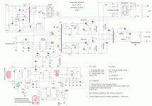
PS - I'll have a look at that schematic you attached as soon as a get a chance. :)
 

kees54

kees57
Hi

Thanks for your extensive reaction.

I do now that aluminium is a problem, but it is not really needed for me, I did mention only, I have include schematics where there are also schematics
of mig inverters in the zip file..

I did though that include wire feed in the feedback loop want to stabilize the process, I have seen on the internet forward mma welders made by a guy who
did also made a supply for normal use 3-30 volts 40 amps with the same schematics.

I did find a full bridge inverter who can do two processes both with one machine, I want use it for car welding and make houses for audio amplifier and other hobby projects, for last one I want to make a spot welder that is also nice for spotwelding car.

Aluminium seen your reaction is not for me, that need extensive current who can not be delivered by a normal household supply (220v) but metal is fine, a source with both current regulator pot and a voltage regulator knop I can use for it, when do MIG a capacitor bank is switched on the output for proper regulation of voltage for mig and when tig or mma capacitor bank is switched of and voltage pot set to max and current pot for regulation current source, so when mig I put current pot to max and use voltage pot for use as volatge source with current as a max protection.

The zip file have multiple schematics also of a caddymig C160i inverter welder for mig. the inverter_popis.pdf is such a multi welder schematic from a diy designer, I need only for MIG use so the current part can be removed, the picture I did send here is also easy to convert when use a comparator in the feedback line, now it is open voltage and set some elco,s on the output for welding, A full bridge fase shift is maybe even better, but for hobby welding this schematic is proberly enough.

I did lone a cheap mig welder from a friend who has no real dc, I have upgrade it for him as a thanks for the lone, puuting in a 20.000 uf cap in it, then it did weld very nice.

Thanks for your advise, I did really learn from it.

regards

kees

ScreenHunter_515 Apr. 20 12.35.jpgScreenHunter_513 Apr. 14 14.56.jpgDSCN2109.JPG

View attachment invertor_popis.pdf
 
Last edited:

blasphemy000

New member
I'm not sure about the power output on a MIG but for a TIG/MMA machine with a properly designed PFC pre-converter, you should be able to get 300-325A of output current in TIG mode, 250A output in MMA mode, with an open circuit voltage of ~70VDC(Output voltage drops significantly while actually welding), while keeping the current draw from the 220-240VAC mains under 50A. Inrush current will be very close to that, but operating current should be a tiny bit less. For a TIG/MMA machine _without_ a PFC pre-converter, 250A in TIG mode, 200A in MMA mode, OCV @ ~70VDC, 220-240VAC Mains inrush and operating current draw should be just slightly less than my first example. These examples are based on the power output and power consumption figured of the Everlast PowerTIG 325EXT(Welder with PFC) and the Everlast PowerTIG 250EX(Welder without PFC). These are budget-priced, inverter welding machines that are manufactured cheaply in China. With a well thought out design and some experimentation, these kind of results should be achievable with a home-built machine. I am unsure what switching topology they are using for the main transformer, but with that kind of power output, I would assume it is some type of full-bridge IGBT design.
 

kees54

kees57
Hi

The Caddymig 160i has a pfc in the machine, this machine has no output capacitors so there are ac there but it
is a mig welder inverter who have wire feed driver as a part of the feedback, with this way the arc stay always
constant special when people have not a moveless hand.

The other way is what you say earlyer a decent dc inverter with dc feedback to keep voltage constant.

The welder who is made by a diy person has dc feedback and when dc pot max open it switch to mma/tig automatically
when put current pot max it switch back to mig. It is a full bridge, I go drawn a schematic of a welder with fase shift
zvp inverter, these are switching softly.

I do not need 330 amps, I do use it for household work like bycicles and old cars, I have max 16 amp 220v socket or
three fase 380, but 380 is not activated and not needed.

I do like the way these things work, I have already a trafo 71/33/32 core at hand to wind.

regards

kees
 

blasphemy000

New member
Your goal of 160A output should be achievable with only a 220VAC @ 16A outlet. Shouldn't be a problem. Inrush current might be slightly over that for a split second, but with a PFC pre-converter, that should be minimal. Everlast's PowerTIG 185 outputs 185A in TIG mode with a listed current draw of 14.4A from the 220V mains. Inrush current is listed as ~24A, but keep in mind, this machine does not have PFC.

I finally had a chance to go over the schematics of that CaddyMig that were in that ZIP file you posted. It is very interesting how they have designed the power supply and after reading some of the descriptions and studying the schematics, I now understand why they have the wire-feed motor in the feedback loop. Allow me to explain how that CaddyMIG is working.

I will be explaining the operation of the dual-power-module model(Schematic on Page 9 of the PDF file), but the single-module version's function is basically identical and the differences are easily to spot on the schematics. The descriptions of operation in that PDF file were very informative, but they were very technical about some aspects of operation, and left out certain parts. After studying the schematic I've come up with a way to explain it's operation in a way that hopefully anyone can understand. Just in case there are other people interested besides you and I.

1.) Input Stage & PFC Pre-Convertor:
The way they have designed the input stage is quite genius when it comes to how they are minimizing the inrush current when the mains power switch is first turned on. I like their concept that I might implement it into my own design if I ever get back to working on it. When the main power switch is turned on, the mains voltage is rectified via diodes MV3 & MV4 for the "GND" rail. The DC BUS storage caps(C2, C21, C22) are given their initial positive charge through diodes V01 & V02, current is limited through series-connected thermistors B01 & B02. This current is then passed through the PFC Boost Inductor(L3) and the Boost Diodes MV7, 8, 9, & 10 and into the storage caps. This process limits the inrush current when the power is first applied via the switch. Once the voltage on the DC BUS reaches a certain voltage(If I understood correctly approximately 280VDC), the Auxiliary supply provides gate/trigger signals to the MV1 and MV2 thyristors(SCRs). Once these SCRs are turned on, they form the high-current full-wave mains rectifier that feeds the PFC Boost converter. After the SCRs activate, the DC BUS storage caps instantly(almost) charge up to the rectified mains voltage. The PFC Boost converter turns on very shortly after the SCRs activate and further boost the DC BUS voltage to ~400VDC. According to the schematic this converter runs between 50-70kHz. I'm not sure if it operates at a fixed frequency that is within that range or if the switching frequency oscillates between 50-70kHz to help reduce the harmonics that are reflected back into the mains wiring(this is probably more likely).

2.) High-Power Switching Stage:
This stage consists of a "2-Switch Forward Converter." The main switching devices are MV11 & MV18 along with free-wheeling diodes(to help protect the switches) MV13 & MV16. The diodes MV14 & MV15 make up the "reset diodes" in the switching circuit. The switches MV12 & MV17 are hardwired to be completely disabled if they are present on the board, but, based on the reading, they aren't actually physically installed in the machine. I would assume that this particular power module(based on the schematic) is also used in higher power models of these machines which require a full-bridge switching topology, in which case MV12 & MV17 would be installed on the module and driven 180* out of phase with MV11 & MV18. Anyways, the main switches(MV11 & MV18) are driven by gate-drive-transformer(T04) with each of its two outputs being fed through discrete "pulse-shaping" circuits with a switching frequency of 70kHz. This switching stage drives the high power switching transformer(T01). The high-current secondary output is rectified by diode V07 and diode-pair V09 & V10. The output power is filtered via inductor L04. Also note that the secondary's DC output is setup with a positive ground, as far as the secondary voltage sensing circuitry goes.

Now I'm not going to go any further into explaining the fine details of how all the little parts of this welder is functioning, but I will include this. The reason there are no output capacitors is because this is a Constant-Current DC power source. This is also the reason that the wire-feed motor is part of the feedback loop on the secondary side. The output power is entirely current controlled via the primary-side current transformer T02. From what I could tell, there is absolutely no voltage feedback from the secondary side back to the switching controller for the primary side. The only voltage feedback in this welder is wired into the wire-feed motor controller. This welder essentially works like the "add-on" boxes I described in one of my previous posts except that the CC power source and the auto-adjusting wire feeder are built into the same box. I'm not sure if all SMPS MIG machines are built/designed this way(CC PSU with Automatic Wire-Feed) because this is the only schematic I've ever seen for an inverter MIG machine. The problem with running this type of setup on a transformer machine a couple decades ago was that even though they were CC PSUs, the current output wasn't as rock-solid as you might imagine it to be, and the automatic adjustment of the wire-feed speed just couldn't be controlled fast enough. I guess with a SMPS providing the Constant-Current, the output can be very tightly(fast) regulated at the set current and the wire feed motor in this particular welder is actually controlled using an almost identical PWM chip that the power supply itself is controlled with, meaning the feed rate can potentially respond just as fast as the power supply(this depends on how the control loops are setup). The power supply is using a UC2844 and the feed motor is using a UC2843. The only difference is that the 2844 chip maxes out at just under 50% duty-cycle whereas the 2843 will go nearly to 100%. I guess if it works great, then hell, I can't see any reason against building it that way if you can get it to work.
 

kees54

kees57
Thank you for the extensive explaining about the welder, I have also see that the schematics of this welder
is not complete, but I did see interesting things like wire feedback loop, this is very interesting for keeping
a very stable arc, even with not as steady hands when welding.

I have see there are excist different topologies og smps weld supply, here I do include a schematic of a fase
shift resonant welding inverter from russia, I have also included the popis welder who can do mig and tig/mma

This I did want to split to only use the voltage part and left out other components, but do not shure if I can
do that because it is together needed, on the other way it is handy when I can also do mma welding with it
or tig because I have already the gas valve.

Is it for 160 amps needed to use a full bridge? or is that overkill, the use of a resonant controller like the fase shift
UC 3875 is maybe a very neat idea, fine tune the switch frequentie for the resonant coil being most effective is
a easy way to get it done.

For what concern PFC using a special circuit with a relais against rush in current works fine, the most welders has this
for me it will be enough necause big amps I never using for household welding like cars, I need that it can bel low amperage
for thin metal like a car, I do burn through most of time and I am search for wire who do weld also rusty metal or old
metal, yes I do clean but sometimes it is rest of rust, or old metal, it is there somewhere.

see schematics.
 

Attachments

  • UC3875Application.pdf
    446.9 KB · Views: 98
  • microprocessor-mig invert.zip
    2.2 MB · Views: 136
  • elk-19-2-1-1001-352.pdf
    482.1 KB · Views: 106
  • MIG200.pdf
    583.1 KB · Views: 112
  • noval type inverter.pdf
    1.4 MB · Views: 155
Last edited:

kees54

kees57
Here some soft switching idea,s the new way of efficienty and less stress switch igbt/mosfet..

regards
 

Attachments

  • las inverters.rar
    4.3 MB · Views: 197

kees54

kees57
Hi

I have a schematic from a mig 200 with components, (little strange schematic unknown machine or DIY) I miss puls shaping for gate igbt,s and also I did see this one do also use a wire feedback
sensing wirefeed,(interesting:D) it comes in this case from a 300:1 current coil who is not in series with the output transformer but on the 310 volts input
line for the igbt,s.

Afcourse it is not a matter where it is, on the line input or between the igbt,s and the transformer.

I like the capacitor in series with output transformer, it prevents saturation , I think it is more save, multiple poly capacitors do well.


I like to hear from you, this one can be nice for inspiration.

regards

kees
 

Attachments

  • MIG200.pdf
    583.1 KB · Views: 80
Last edited:

kees54

kees57
This schematic has a real dc voltage feedback, but on a special manner, I think MMA/MIG switch is not
proper drawn because when MIG the voltage feedback input is to ground.

The last LVI based one is really interesting to go testing.

Then make a voltage source is not difficult because it is just a simple dc supply with controlled voltage loop.

Regards and nice weekend.

v8_mmamig.GIF

wire feed but I can not read the syrillic on the schematic. I have the code for the atmel as wel.

you can find it on www.samopal.su

Feed_PWM_v1.JPG

making a trafo? with flat copper strip on secundairy? looks fine in terms of skineffect.

statja-svarka08.jpg

statja-svarka07.jpg
 
Last edited:

kees54

kees57
Hi There


Can someone explane me how to use the outcome of this program into LTspice IV? I am just a very bad calculator guy.

I read something about square root of turns ratio.

I did see in a example 900 mH !! but when use 900 uH is closer to reality 900 mH is a very big inductor who is not usable in
a smps, so I think it means different of so..

Thanks for explaning me. Th K factor and such I do now.

Setting the turns ratio of the transformer
is simply a matter of choosing
the right inductor values. Remember,
the inductance is proportional to the
square of the turns ratio. In the example
above, a turns ratio of 1:3 gives
a 1:9 inductance ratio. How? if I do 1:.3 I get 3.33 square of that gives 1.82.

regards

kees
 

blasphemy000

New member
I don't have time at the moment to go over all of those attachments you posted and look at all of the schematics. For your desired maximum output power of 160A, a full-bridge topology does seem like a bit of overkill and unnecessarily complicated. Component selection and the timing of the switches is slightly more critical with a full-bridge design due to the massive potential power output that it can withstand. It just doesn't seem like the extra components and complications would be worth the effort if your output current will peak at 160A. Honestly, for the power output you desire(160A), I would build a design similar to the schematic for the CaddyMig. A two-switch forward converter is more than ample enough to provide that level of power output and be extremely reliable doing so. You could most likely even achieve that power output without using a PFC Pre-converter, although your current draw from the mains would most likely exceed your limit of 16A, and the harmonics being fed back into the power grid would be very bad and would require a very large amount of storage capacitance on the mains rectifier. The reason I was going with an interleaved full-bridge topology and an interleaved PFC for my TIG design was due to the massive 300-325A output power I was looking for. That's approximately 6500-9500 Watts of power assuming 100% efficiency with a loss-less system which is impossible to implement. I was figuring with the normal amount of losses in a high-power SMPS that my RMS input current at 240VAC mains voltage would be around 50Amps. That's 12kW of input power and that is a lot, although completely achievable if I can get the design elements correct.

Winding the main transformer with copper foil for the secondary is common practice from what I have seen in SMPS welding machines. Your reasoning is correct. It combats the skin effect that you encounter when using large diameter conductors at increased frequencies. The flat copper sheet windings allow for a large amount of current to flow through the conductors while allowing the entire cross-sectional area of the conductor to carry the current. In some of the higher power machines I've seen the secondaries wound with multiple, parallel layers of copper strips, each insulated from each other to provide more current flow while still minimizing the skin effect. This is essentially the same idea as Litz wire.

Calculating the size, number of turns, and turns ratio of your main transformer(and your output inductor) can be kinda complicated if you get too obsessed with the mathmatics of all of it. There is a program in the information section of this forum called ExcellentIT(7100). It usually provides a good starting point as far as figuring out transformer information. Here is the link to the thread: http://www.diysmps.com/forums/showthread.php?522-Calculation-programs-for-transformers-and-inductors
 

kees54

kees57
Thanks for your help, I have enough info to start looking at it, I have also found a atmega8 programmed version who has even a ac
output possibility, and can do mig/tig/mma.

I have download LTspice IV I have already learn it to use, and it is very easy except the coils, I no K1 L8 L9 1 for example but
do not now yet how to calculate the inductions who is proportional of windings, maybe the Al is for use here.

The program for the trafo calculations is known, I have download it a while ago and it works fine.

I go use the copper strip, for primairy I do not now if that is possible because of capacity with flat wire but also the aircap
where that copper can go hot. I go do the secondairy and use 2 x skineffect as thickness because I do calculate fromout middle
of copper and so 2 x in my case with 60 Khz this is 0.539 x 2 is 1 mm thick by 38 = 38 2cm = 7.45 mm because of it is flat
and skin 100 procent, round wire the same calculate skineffect from centre wire and so it is 2 x 0.359 = 1 mm wire for 100
procent. I can get 211 amp chassis wiring and 120 amps power transmission, with a ventilator I get more then enough.


I have to find insulation for the flat wire, so I go search google or a wind company here.

The schematics are maybe of use for you when you go on the project some day, I do place schematics when I find them for you
it is always nice stuff to read, I go smps because I am high end audio designer en want go over to smps in stead of big trafos
these days smps are very good, I need multiple voltages and this csn easely be calculated with thet program.

regards and thanks, I have enough to start, I will post it also here.

kees
 
Last edited:
Top