UC3842 to learn from

EarlGray

Professional Newbie
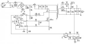
I am new to SMPS and am trying to learn. I wanted to start out small. I took a SMPS that I had using the UC3842. Then drew out the circuit and checked it twice. Then I checked it again :D The only part I am unsure of is D2, it was unmarked. C9, and C10 measured 480pF so I figured they must really be 510pF.

A penny for your thoughts

24V 2.65A SMPS.jpg
 

EarlGray

Professional Newbie
After taking the transformer apart, this is what I came up with.
What do you think?
Can anyone tell me why the second half of the primary does not have the same amount of turns as the first half?

Thank you


24V 2.65A SMPS-Rev3 TR.jpg
 

wally7856

New member
My best guess is that this is a flyback transformer and one of the primary windings is for switching and the other winding is for feedback.
 

EarlGray

Professional Newbie
There are 2 halves of the primary winding. One half has 25 turns the second half has 19 turns. They are just tied together in the center. The feedback/Auxillary/Bias Winding (whatever it is called) is a separate 6 turn winding. The transformer has a 25 turn half of the primary winding, then the secondary winding, followed by 19 turns of the second half of the primary. Then an additional 6 turn feedback winding.
 

wally7856

New member
2nd best guess, maybe the first primary was fully wound across the core so the secondary would have a full base to be wound on.

Physically, how was the 2nd primary and 6 turn bias winding wound. Were they on one end of the core or were the windings spread out for both of them across the whole core.
 

EarlGray

Professional Newbie
Physically there was the 25 turn half primary wound around the bobbin (PQ2620), then 3 layers of tape. Second was the 8 turn secondary, and 3 layers of tape. Third there was the 19 turn second half of the primary, and 3 layers of tape. Last was the 6 turns for the bias winding in the center of the bobbin, followed by 3 layers of tape. So we have primary, secondary, primary and bias.
 

KX36

New member
I can't say why it was done like this, but there's nothing that says splitting a primary winding to interleave it has to have the same number of turns on each primary layer, so I would presume it was done for some manufacturing reason or it's a relic of the prototype or something.

There's also probably no reason for 3 layers of tape between the outer primary layer and the primary bias layer as there is only a requirement for functional insulation between 2 primary windings 1 layer would have been sufficient.

Flyback transformers, not really being transformers but linked inductors with multiple windings, can have some odd behaviour in the time it transitions from charging through one winding to discharging through the rest. Depending on coupling and leakages, they preferentially discharge through one of the windings first and so you may see things to try to help balance it and make it discharge preferentially though the main secondary power output winding rather than a bias winding. There's an off chance it's something to do with this but I doubt it. The secondary being between the primaries and R7 on the bias winding would be taking care of that.

It looks like a pretty standard flyback converter, I'd be happy to explain any part of the circuit if you get stuck. The only information missing really is the transfomer inductances and gap size, not easy things to measure.

Interesting you assume caps that measure 480pF are meant to be 510pF. I would have assumed 470pF, but it only really matters what they measure.
 
Last edited:

EarlGray

Professional Newbie
Thank you for your reply. I had measured inductances before taking it apart. The primary inductance measured 750uH, The secondary measured 25-26uH and the bias measured 15-16uH. Using a feeler gauge, the gap was .015-.016" Hows that? :D
My original thought on the cap was that the measured capacitance would be lower than the marked capacitance. I didn't think until after that it could be the other way around. I thought that if the 510pF didn't work, I'd try the 470pF.
 

KX36

New member
Well that's a pretty complete picture of the device then. :D The inductance ratio matches up to the turns ratio as it should. The tolerance of the capacitors is probably wide enough that 470pF vs 510pF is irrelevant. One capacitor filters the leading edge spike off the current sense, the other would be passing some oscillator ramp to the current sense pin for slope compensation so its unlikely either is a highly critical value, although they will affect the switching frequency that's unlikely to be critical either.
 

wally7856

New member
KX36, how did you determine this.

"The inductance ratio matches up to the turns ratio as it should."

Primary 25 + 19 = 44 turns
Secondary = 8 turns
44 / 8 = 5.5

"The primary inductance measured 750uH, The secondary measured 25-26uH"
750 / 26 = 28.8
 
Top