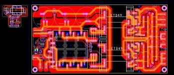
1kW smps project (based on MicrosiM design)

MicrosiM

Administrator
Staff member
hi microsim, i found the problem, the osc small transformer one wire short with other wire,
now its working perfectly,
can u give me the transformer formula update one in excel, u already post that but its not opening in my excel.
microsim i saw one smps the primary and secondary same wire strands (4 wire stran for pri and 4 for sec) same gage, is it ok?

You have to tell me witch version of excel you are using. both versions are at the forums
 

nazirdigi

New member
in the update rar folder this is the file have (Transformer_Formula.xlsx) its not opening in my excel. excel 2003 version.
 

zoliph

New member
hi all!
Sorry for my English.:)
This is my first post in this forum, I'm also interested to make this SMPS project, please help to avoid future missteps, and therefore there are some questions that are still confusing me :(, it is:
1. If I do not find the right core, what alternative instead?. I have a core with size (/ - L * H * W) 49 * 27 * 17mm, what can be used?:confused:
2. I have two sizes of wire, 0.1mm and 0.4mm, which is suitable for the core?
3. If they fit or can be used, how the turn and strand should I make to the primary side and secondary side?, In this case the target is a symmetrical output +-75V /and +-50V.
4. What transformers are used to supply the SG and IR?, Could use a non-sealed transformer or from the main transformer? and why?
5. Can someone explain about the details Current transformer? (About cores are used, the wire size, number of turns, the jumper through current transformers, etc.).
6. In PWM circuit there are two trimmer (R12 & R13) and there is another one in the protected module (R5), what is its function?, And how to set it? ...
7. What is the total value of micro (u) capacitor (min) for each output rails?
8. What is the minimum value of amperes at Relay?
9. What kind of load used to test this project?, Maybe a lightbulb? Minimum or maximum number of Watt or the Ohm?
10. What about efficiency, the normal temperature of the FETs with or without a load, and can i see the complete scheme of this project as a reference source?
Thank you.:UP:
Regards...
 

A square

New member
hello frnds .... i m makeing this smps but i have etd39 core .... for 40v -0-40v dc what is the turns ??? with etd39 what how many whats i can get at 40-0-40v dc ... pls help ...
 

P.S.RAJU

Member
hello sir microsim
I made your smps 1kv based on microsim , i made transformer winding of etd49 the voltage output is 50volt with out load ,but when i connect a load of 150watt amplifer the volt dropes to 30 volt at peak out put,so plse help me
 

P.S.RAJU

Member
Hello sir microsim
My voltage drop problem was solved,the capaciter 1uf 400volt was defective. now i get full volt of +/- 50.
I replaced the mosfet to IGBT GRPC 50U ,the IGBT gets warm with out the output dc load . circuit is 1kv smps based on
microsim designed ludo,half bridge.
can i use the same design to increase the smps wattage to 5kvusing IGBT
can i use transformer etd59 instead of etd49 to increase the wattage
i dont know the primary and secondry winding
so please tell me the winding detial

can this 1kv smps be made regulated if yes then send me the modification schematic
thank you
 
Last edited:

MicrosiM

Administrator
Staff member
Please see answers below..

Hello sir microsim
My voltage drop problem was solved,the capaciter 1uf 400volt was defective. now i get full volt of +/- 50.
I replaced the mosfet to IGBT GRPC 50U ,the IGBT gets warm with out the output dc load . circuit is 1kv smps based on
microsim designed ludo,half bridge.

Please check your Dead Time settings.

can i use the same design to increase the smps wattage to 5kvusing IGBT

You can increase the power to 5KW if you use ETD59, and 75A IGBTs, LITz wire, and at least 125KHz.

can i use transformer etd59 instead of etd49 to increase the wattage

Yes you can

i dont know the primary and secondry winding

I need to know your secondary voltage to give you details of windings..

so please tell me the winding detial

can this 1kv smps be made regulated if yes then send me the modification schematic
thank you
 

P.S.RAJU

Member
Hello sir microsim

I Need windng detial of etd 59 my voltage is +/- 80v 15amp & +/-160,15amp .
this is my first smps of (high amp) so pls tell me how to adjust dead time and frequancy.
I use copper wire off 1mm for primary & secondry winding off ur design based on microsim 1kv
useing 2110 & sg3525 and etd 49 , I used igbt instead of fet the supply is +/-50volt,iwant to know
how much amp of +/-50volt will give &how much wattage will it go to maximam.
can this circuit be regulated,because,i want to know wheather it works from 180 to 230 volt ac if yes plse give
me the modification of schematic.
thank you
 

P.S.RAJU

Member
Hello sir microsim

I Need windng detial of etd 59 my voltage is +/- 80v 15amp & +/-160,15amp .
this is my first smps of (high amp) so pls tell me how to adjust dead time and frequancy.
I use copper wire off 1mm for primary secondry winding off ur design base on microsim 1kv
useing 2110 & sg3525 and etd 49 , I used igbt instead of fet the supply is +/-50volt,iwant to know
how much amp of +/-50volt will give &how much wattage will it go to maximam.
can this circuit be regulated,because,i want to know wheather it works from 180 to 230 volt ac if yes plse give
me the modification of schematic.
thank you
 

P.S.RAJU

Member
Hello sir microsim

I Need windng detial of etd 59 my voltage is +/- 80v 15amp & +/-160,15amp .
this is my first smps of (high amp) so pls tell me how to adjust dead time and frequancy.
I use copper wire off 1mm for primary & secondry winding off ur design based on microsim 1kv
useing 2110 & sg3525 and etd 49 , I used igbt instead of fet the supply is +/-50volt,iwant to know
how much amp of +/-50volt will give &how much wattage will it go to maximam.
can this circuit be regulated,because,i want to know wheather it works from 180 to 230 volt ac if yes plse give
me the modification of schematic.
thank you
 

phoenix

New member
smps half bridge irfp460 layout

please share this smps half bridge irfp460 smps single
sided schematic layout (post #741) sir stewin. Thanks
 
Last edited:

hoangdao2030

New member
smps by detex audio
warm regards
michelle

Hi michelle!

I'm also building a circuit pulse power supply circuit according to this principle. but now I have a problem is only 30kHz oscillator frequency. Can you tell me how to increase the frequency of oscillation.

This is my pcb.


Thanks!
 

Attachments

  • smpsnew.jpg
    smpsnew.jpg
    284.2 KB · Views: 534

ludo3232

Member
last beta design no tested!

Hi all.

I have decided to definitely abandon smps dev.

i no have time and money for this, but i share my last design.

it's regulated smps, short circuit protected and over-voltage shutdown.
work with a GDT to provide isolation of primary side.

WARNING! This smps is not tested, i never made the pcb, only the drawing and simulation.

I post the eagles files. i hope this help people to make SMPS

View attachment smps 3525 GDT beta v4.00 no tested.zip

I do no provide any support for this smps, i no have the time and it's never tested in real life.

Bye
Ludo3232
 

antonamp

New member
Hi to all of you. My name is Anton from Bosnia and Herzegovina.

I hava plan to build this SMPS declared like 1kW, but I need more power. I need at lest 2,5kW SMPS for my H-Class amp APEX H900 and that mean I need four secondaries on transformer and thats OK. I am wondering can I increase the power of SMPS with using larger transformer core like E55 and replacing IRF460 with IGBTs IRG4PC50U as well???

QSC PLX3402 SMPS uses them and I want to make something like this. Also that QSC SMPS uses IR2110, SG3525 and E55 core like this one.

Thank you
 

ragaman

New member
1. How the supply voltage is maintained at the specified value if there is no feedback/regulation? Does that mean that the SG3525 is working at a duty cycle of 50%?

Yes, 50% duty cycle.
Voltage change is done by changing transformer winding's ratio.


2. What's the efficiency of this SMPS and it's power consumption at low load? (This is an important fact for myself)

Ludo Can answer this, but I think its around 85~ 90%

3. If i use an ETD44 instead of ETD49, will a be able to get a power between 500-700W?

ETD44 will hit 800W very easy.


Hope that helps

Hi Micro, I have a question, the duty cycle always should work on 50% for not regulated smps ? whats happen if my SG not give me more than 47% DT ?
 
Top