1kW smps project (based on MicrosiM design)

joryds

New member
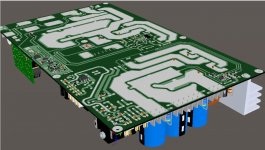
Hello fellow MicroSIM, I have a doubt in the calculation of ETD49 I'm testing on the source that is observed in the catch.

For a frequency of 82 kHz, 16 embark in the primary windings, and the secondary for 8 +8 + /-80V.

The core material is Ferroxcube 3C90.

When I have 326V / 2 = 163DC in the primary, the secondary leaves + /-88V DC without load.

This is within the normal?
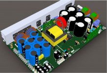
Smps-joryds-01.JPG Smps-joryds-02.JPG
 
Last edited:

MicrosiM

Administrator
Staff member
Looks nice commercial product ;)

Yes voltages seems normal, you have to adjust your windings to get +-80V
 

joryds

New member
Hi MicroSIM, thanks for your response.

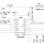
To work with a resonant source is essential to use the sync pin 3?

What problems have the source if not synchronize?

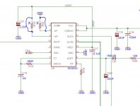
In the shoulder catch on pin 1 and pin 2 a bridge as I observed in commercial smps, what would be the advantage of placing 1K resistors in the pin1 and 2?

Greetings ...

pwm jd.JPG pwm jd 2.JPG
 
Last edited:

MicrosiM

Administrator
Staff member
Very good questions.

yes you have to sync the SG3525 in resonant SMPS, becasue resonant SMPS woks in a fixed frequency window. and if the frequency changes, problems will start.

Regards
 

nazirdigi

New member
hi microsim, which method is good for winding cores,etd49
1-with single copper wire (thick 1.8mm) primary 24 turns and secondary(1.6mm) 1 turn for 6.2v.
2-multi strand wires (thick .65mm) primary 4wires 24 turns and 6 wires secondary for 1turn 6.2v

if this wrong calculation pls correct this.
 

MicrosiM

Administrator
Staff member
hi microsim, which method is good for winding cores,etd49
1-with single copper wire (thick 1.8mm) primary 24 turns and secondary(1.6mm) 1 turn for 6.2v.
2-multi strand wires (thick .65mm) primary 4wires 24 turns and 6 wires secondary for 1turn 6.2v

if this wrong calculation pls correct this.

Its always best to use multi strands, like 0.1mm for better results.

You can use single wire, but with heavy loads it will heat like hell.


Regards
 

nazirdigi

New member
smps 1.2kw

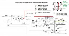
thanks microsim for the reply,in this schematic their mention the wire size in mm, if i wind with small gage wire with multistrand ,what are the size i have to get maximum power.how many turns for primary230vac and secondary +95,0,-95vdc?
 

Attachments

  • 1.2KVA.jpg
    1.2KVA.jpg
    237.4 KB · Views: 233

nazirdigi

New member
thank u microsim .
i am going to wind with multistrand so
pls give wire gage and turns for primary and secondary.
 
Last edited:

nazirdigi

New member
thanks microsim, but u didnt mention the wire gage for multistrand winding for primary and secondary.

secondary 12.5 turn for 95vdc am i right.?

i an expecting ur reply micosim.
 
Last edited:

joryds

New member
Hello MicroSIM, in theory it 20 laps 10 + 10 but in the secondary coil with 10 turns get 82V with 11 91V and 100V with 12 turns almost.

This test did not load with a voltage of 330V DC in the mosfet is, 165V on the primary.

Greetings ...
 

MicrosiM

Administrator
Staff member
Ok

Exact result is

ETD 49 running at 70KHZ, primary voltage 165V, and Bmax 1400G

Primary 10+10 Turns

secondary for +-95 vdc you need 11.5 + 11.5 turns

for +-91 vdc you need 11 + 11 turns

all calculations for UNREGULATED SMPS.

this is 98% accurate calculations

regards
 

nazirdigi

New member
hi microsim, one problem,
if one turn 8.2dcv then how can i get 12v for the relay, so 2 turns will come 16.4vdc ,
so what is the calculation for 1 turn 6.2vdc.?
can i use 0.71mm gage 4 strand *24turns for primary and 6 strand * 15 + 15 turn for secondary.
 

MicrosiM

Administrator
Staff member
hi microsim, one problem,
if one turn 8.2dcv then how can i get 12v for the relay, so 2 turns will come 16.4vdc ,
so what is the calculation for 1 turn 6.2vdc.?
can i use 0.71mm gage 4 strand *24turns for primary and 6 strand * 15 + 15 turn for secondary.

I think you can use 3 turns for relay, and use 1 transistor 1 Zener to regulate it to 12VDC or use a 24VDC relay.

You can start with the wires you have on hand and see results.

Regards
 

nazirdigi

New member
hi microsim,
i finished my smps 1.2kw,
but when i power on some noise is coming like (snooze). but the series bulb is normal state when i power on, then i removed the secondary rectifiers and i checked, then no noise,what will be the problem?
 

joryds

New member
Hello MicroSIM, to implement the current sensor, which is in turn the SMPS rapidly in a short circuit, that kind of setup did you use or what can you recommend me?

I did tests with the LM393 + LM555 but I notice that the LM393 has 200NS very slow and I think what you think.

Greetings ...
 

MicrosiM

Administrator
Staff member
Hello MicroSIM, to implement the current sensor, which is in turn the SMPS rapidly in a short circuit, that kind of setup did you use or what can you recommend me?

I did tests with the LM393 + LM555 but I notice that the LM393 has 200NS very slow and I think what you think.

Greetings ...


I cant see any problem with that combination of ICs, they work just perfect.
 

nazirdigi

New member
hi microsim, i found the problem, the osc small transformer one wire short with other wire,
now its working perfectly,
can u give me the transformer formula update one in excel, u already post that but its not opening in my excel.
microsim i saw one smps the primary and secondary same wire strands (4 wire stran for pri and 4 for sec) same gage, is it ok?
 
Top