Gate Drive Transformer Issues

Jagd.Panther

New member
The spikes going from SG3525 in my full bridge layout are still mystery
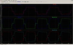
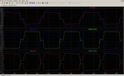
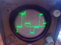
If you are using 1:10 or 1:100 probe you have to calibrate it first (usually oscilloscopes have dedicated output to do that, if yours dont just hook up the probe to any source of square wave with fast enough rise/fall times, ir2153 low side output will be more than enough for your scope).

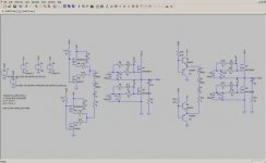
SG3525 outputs clean square wave signals, I measured 80ns rise 30ns fall time (IIRC it was ca. 100pF load) for an old Fairchilds SG3525 @ 12v. It's designed to do that and it does precisely that. If you see anything but clean square wave on SG3525 output it's something that happens after it (most likely it's either a lower mosfet due to Cgd when upper mosfet is turned on or vice versa or leakage/magnetizing inductance of the GDT shooting through BJT junctions back to SG3525 outputs, that could also happen when there are loops with high di/dt and issues with layout but your full bridge is not loaded so thats unlikely)
 

lynxlynx

A rumbling soft motor
Hm, on IR2153 it shows nice clean square wave with rise and fall curves almost absent (a great reference), no spikes or other distorts. The scope is really old. That's why I lean towards using IR2110 in low voltage project - they output nice clean square waves with known rise and fall times, and free duty cycle control. As for high voltage, I have another unisolated IR2110 circuit in mind which bootstraps from high voltage transistor and gets it's supply from aux. winding of main transformer later. But it's pain then not connecting grounds of IC and output and having voltage feedback through optocoupler and tl431 with voltages above 36v. At least I want to keep input and output isolated, no matter how.

When I had spike after driver, I had not them at outputs of SG3525 (maybe because of already present RC filter). I trust this scope when I need to see generic waveform without trying to tell waveform parameters.
 
Last edited:

Jagd.Panther

New member
Lynx, I suggest you to consider two transistor forward converter. Simpler design, no cross conduction by design (this translates to relaxed requirement to drivers).
 

lynxlynx

A rumbling soft motor
Well this one I will not abandon because I wanted to discover how GDT works. Once I will complete it, it will be easier for me to build others. So this one even if will not finished today, but will be finished when I will get required equipment which I hope will happen soon. Thanks for suggestion, but it's harder for me to understand how non-AC circuits work (for example, flyback converter is still hard for me to calculate rather than high frequency AC transformers which are way tooo easier to test in reality).

And I am not sure will I be able to pass-through at least 700W @ 55Vout and in future, 2kW with N87 toroidal core with two transistor forward converter, what are requirements to switches and transformer core, does it need gap or not etc.

Cheers!
 
Last edited:

lynxlynx

A rumbling soft motor
Ooops -- big sorry about snubber cap specification - I misread - it was 10nF instead (103).
If someone will use that thread for a reference then I am sorry about specifying wrong part.
 

Jagd.Panther

New member
If you are set on GDT and FB, here are few tips:

- Ditch emitter followers. Use p- and n-mosfets(like irfd110/irfd9120, Rg ~10-20) pair for every output. Don't forget to add a local cap on Vdd. To limit output current and losses on cross conduction use two low ohm (~1ohm +) resistors from sources to output.
- Don't use large series resistor for GDT's prrimary. In fact, don't use any if you have installed resistors from fet's drains to driver output.
- Try to minimize leakage inductance, i.e. keep number of turn on GDT core.
- Use local drivers to keep fet/igbt closed (like a pnp that pulls gate down) and to improve dv/dt immunity
- duty cycle & dead time time control should be enough to prevent cross-conduction.
 

lynxlynx

A rumbling soft motor
Yesterday I was in krai center and bought four 17x8x5 tiny Russian ferrite cores. They're all M2000NM1 type (a Soviet power ferrite type) with 0,2T max density. I tested one today and there good news I think: they require only 10 turns (my unknown one heats up to 50C with 14 turns), they cool on 50kHz and burn resistors and thin nails to red with thick coil. I plan to wind one with UTP5 wires and play with it in my circuit. The only problem with them is sharp edges.

Jagd.Panther, can a regular IRFZ24N/IRF4905 can be served as drop-in replacement for BD139/BD140 in my circuit? I also searched the web and found this circuit with both drivers stacked: totem-pole drives driver fets and they drive GDT.

Thanks for your suggestions, I will keep them in mind with my next designs!
 

Attachments

  • GP_inverter_GRAND.GIF
    GP_inverter_GRAND.GIF
    16 KB · Views: 135

MicrosiM

Administrator
Staff member
Yesterday I was in krai center and bought four 17x8x5 tiny Russian ferrite cores. They're all M2000NM1 type (a Soviet power ferrite type) with 0,2T max density. I tested one today and there good news I think: they require only 10 turns (my unknown one heats up to 50C with 14 turns), they cool on 50kHz and burn resistors and thin nails to red with thick coil. I plan to wind one with UTP5 wires and play with it in my circuit. The only problem with them is sharp edges.

Jagd.Panther, can a regular IRFZ24N/IRF4905 can be served as drop-in replacement for BD139/BD140 in my circuit? I also searched the web and found this circuit with both drivers stacked: totem-pole drives driver fets and they drive GDT.

Thanks for your suggestions, I will keep them in mind with my next designs!


I am able to drive two mosfets without any totem pole, for up to 700W power from my SMPS. with very nice wave shape, and very stable design.

I don't think using Mosfets will make that difference, stay with BDs as start.

Regards
 

Jagd.Panther

New member
Jagd.Panther, can a regular IRFZ24N/IRF4905 can be served as drop-in replacement for BD139/BD140 in my circuit?
IRFZ24N - yes
IRF4905 - nope, it's too overkill for the job. Try to find something like: IRF5120, IRFF9Z24(N), IRF9Z34(N).


I also searched the web and found this circuit with both drivers stacked: totem-pole drives driver fets and they drive GDT.
Overkill for SG3525 (SG3525 has totem-pole output while TL494 doesnt).
 

Jagd.Panther

New member
attaching examples of GDT driver circuits. Complementary BJT Emitter Followers vs Mosfets.
 

Attachments

  • 1.jpg
    1.jpg
    19.1 KB · Views: 72
  • 2.jpg
    2.jpg
    18.7 KB · Views: 116
  • 1.jpg
    1.jpg
    337.6 KB · Views: 67
  • 2.jpg
    2.jpg
    138.1 KB · Views: 79
Last edited:

lynxlynx

A rumbling soft motor
Good news - new cores work super nice!

I wound 10 turns around this and it works, I attach a working wave taken from first high mosfet. It's under light load (50W). I'm getting same waveforms when I simulate my circuit in LTSpice. So I trust it.
Thanks anyone who had patience to help me. I learned the lesson: not all garbage cores work nice.

The remaining problem is flyback supply, it is unstable. I will wait for LC meter to be shipped, and I already prepared it separate to have fun with. wiz:;
 

Attachments

  • 101.jpg
    101.jpg
    52.4 KB · Views: 43
  • 102.jpg
    102.jpg
    70.9 KB · Views: 63

Jagd.Panther

New member
Hi Lynxlynx, it's dangerous to wind a GDT with magnet wire like you have on the pic, you must have enough isolation between windings to withstand 2kv+ at HF. AC You can use triple insulated magnet wire/heavy insulated magnet wire, hook up wire with PTFE isolation, whatever you have available. You can combine different wires together, for example magnet wire for 1 winding and heavy insulated magnet wire for the rest(2 and 3 windings).

Also the gate waveform looks asymmetrical for some reason
 

lynxlynx

A rumbling soft motor
Hi Jagd.Panther!

Yes I understand that insulation is not very nice however anything insulated I have is only UTP5 cable which I tried already and it was hard to put all 10 turns inside. When I've done, I seen the insulation failed and some windings had been electrically connected through core. I think it maybe good, but only for half bridge (minus 2 windings).

I however can make another one since this works nice, with every winding insulated. It still has a good free window.

I've shown waveform when feedback was connected and shown duty cycle is less than 50%. Mosfets are properly driven, no shoots or overcurrents. Nothing heats much.

I see same waveform when I simulate (crudely) it in LTSpice.
 

Jagd.Panther

New member
Hi Jagd.Panther!

Yes I understand that insulation is not very nice however anything insulated I have is only UTP5 cable which I tried already and it was hard to put all 10 turns inside. When I've done, I seen the insulation failed and some windings had been electrically connected through core. I think it maybe good, but only for half bridge (minus 2 windings).

I'd use a sandpaper or a file to smooth sharp corners on the cores you have.

Also you can do 1) stack two cores together and use half of turns 2) use two GDT, one for each leg.


I however can make another one since this works nice, with every winding insulated. It still has a good free window.

I've shown waveform when feedback was connected and shown duty cycle is less than 50%. Mosfets are properly driven, no shoots or overcurrents. Nothing heats much.

I see same waveform when I simulate (crudely) it in LTSpice.
Do you have any zeners on the fets? The negative part of the waveform looks like it's clipped by something
 

Jagd.Panther

New member
Lynx, the waveforms you took look kinda strange. Like the beam goes from right to instead of left to right. Did you try to probe ramp signal (Ct) on SG3525? How does it look?
 

lynxlynx

A rumbling soft motor
I'd use a sandpaper or a file to smooth sharp corners on the cores you have.

Also you can do 1) stack two cores together and use half of turns 2) use two GDT, one for each leg.


Do you have any zeners on the fets? The negative part of the waveform looks like it's clipped by something

I don't see anything unusual, but according to simulation, there is no harm, fets don't go upper than 2V. Is there anything strange?
I attach my current simulation and screenshot.

Yes I have 1N4746 zeners in both directions.

Lynx, the waveforms you took look kinda strange. Like the beam goes from right to instead of left to right. Did you try to probe ramp signal (Ct) on SG3525? How does it look?

I believe the scope direction goes from left to right. I will be able to take signal only tomorrow.

Thank you for your suggestions. I hope I will redo the gdt.
 

Attachments

  • gdt_model.zip
    1.9 KB · Views: 53
  • 103.jpg
    103.jpg
    18.3 KB · Views: 57

Jagd.Panther

New member
I don't see anything unusual, but according to simulation, there is no harm, fets don't go upper than 2V. Is there anything strange?
I attach my current simulation and screenshot.

Voltage spike caused by Ls/Llk discharge must be on leading edge of the pulse, while you have it on trailing edge.
Top part of the pulse should have slight tilt caused by finite Lm, it decays with time, while on your pics it's raising.
You feed GDT with BJT emitter followers, voltage at dead time should be positive just before the leading edge of the positive pulse, and negative after the trailing edge of the positive pulse, while on your wave form it's vice versa.

Yes I have 1N4746 zeners in both directions.
Back to back or anti-parallel?
I believe the scope direction goes from left to right. I will be able to take signal only tomorrow.
It should be like that.
 

lynxlynx

A rumbling soft motor
Voltage spike caused by Ls/Llk discharge must be on leading edge of the pulse, while you have it on trailing edge.
Top part of the pulse should have slight tilt caused by finite Lm, it decays with time, while on your pics it's raising.
You feed GDT with BJT emitter followers, voltage at dead time should be positive just before the leading edge of the positive pulse, and negative after the trailing edge of the positive pulse, while on your wave form it's vice versa.
Sorry I will not able to tell you now because you were right about GDT insulation. Today when testing I encountered a spark near it (maybe inside it) but it continued to work. I hope nothing damaged. I do not test it since then. I will rewind it with insulation today.

Back to back or anti-parallel?
Back to back, as in my simulation.
 
Last edited:
Top