1kW smps project (based on MicrosiM design)

Jagd.Panther

New member
The PCB layout is subpar, traces for gate drive & return are suboptimal (need to reduce loop area). Ground and bypass caps placement near SG3525 aren't optimal as well. Caps should be closer to the chip, traces should be shorter, etc
 

Jagd.Panther

New member
it's up to you

I'd start with mods on SG3525 and ground (heatsink, connecting hv and lv grounds with a cap), then proceed with the rest.
 
Hello Jagd.Panther

I connect the heatsink to the low voltage ground and now the voltage get to 172V (Like when I connect oscilloscope to smps)
 
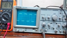
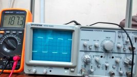
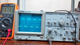
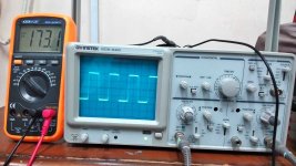
here's oscilloscope pictures from secondary of transformer with heatsink connected to low voltage ground ( middle pin of LM7815)

Without any load connected to output:
Rail one: 15.jpg
Rail two: 16.jpg


With about 450W power drawn from output:
Rail one: 17.jpg
Rail two: 18.jpg

high Voltage drops are due to low capacitance in input and output stage (680uf in input and 2000uf in output each rails)
 
test transformer under very light load. It should be barely warm

Hello "Jagd.Panther "
I did what you told me to do and test the smps under very light load (about 25w) and here's the results:

In about 30 minutes:
Transformer cores temp >> 63"c
Transformer windings temp >> 47"c
All other parts temp was at room temperature

In about 1 hour:
Transformer cores temp >> 66"c
Transformer windings temp >> 47"c
All other parts temp still was at room temperature


I repeat the test for 500w load and the results are:

In about 30 minutes:
Transformer cores temp >> 63"c
Transformer windings temp >> 51"c
Output diodes body temp >> 45"c
IGBTs body temp >> 55"c
Heatsink temp >> 45"c
Above temp is without any fan around the smps and with a room temperature of 32"c


In about 1 hour:
Transformer cores temp >> 66"c
Transformer windings temp >> 56"c
Output diodes body temp >> 50"c
IGBTs body temp >> 62"c
Heatsink temp >> 50"c
Above temp is also without any fan around the smps and with a room temperature of 33"c
 
I set the frequency to 40khz and measured its heating

In about 30 minutes:
Transformer cores temp >> 89"c
Transformer windings temp >> 67"c
Output diodes body temp >> 45"c
IGBTs body temp >> 48"c
Heatsink temp >> 42"c
Above temp is without any fan around the smps and with a room temperature of 29"c


In about 1 hour:
Transformer cores temp >> 92"c
Transformer windings temp >> 72"c
Output diodes body temp >> 45"c
IGBTs body temp >> 50"c
Heatsink temp >> 45"c
Above temp is also without any fan around the smps and with a room temperature of 30"c
 

Jagd.Panther

New member
40khz is way to low for the transformer you made. Don't run it like that.

If you have +30degC temperature rise on idle w/o forced air cooling that basically means the trafo requires forced cooling, or you have to use a bigger core. You can also add more turns to reduce losses in the core, but that will cause more losses in the windings under full load (assuming you will have to decrease wire crossection).

thank you for your helps

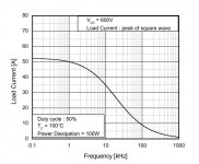
but I did this because I saw below chart on the IGBTs datasheet that I used (FGL40N120AND)
1.jpg
Am I wrong?
 
If you have +30degC temperature rise on idle w/o forced air cooling that basically means the trafo requires forced cooling, or you have to use a bigger core.

I have ETD59 too
Can I use that core? because I want to deliver +-80 and +-40 and +-12 volt rails
I can't fit these whole winding on ETD49
What do you think about the working frequency? should I change my IGBTs?
 
Top