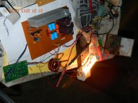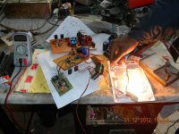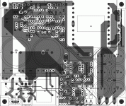
1kW smps project (based on MicrosiM design)

MicrosiM

Administrator
Staff member
ill make pcb of ludo SG+2110 ver3.11 ill post it if i made it pls guide me ty
all parts is ready except mur1560 i can only get MUR3060ct and STPR1620
ang my aux trapo is 20volts ac could this work?

is the litz wire 1.7 mm ok?

one more thing what would you suggest to make Ver3.11 or 2.1 Sir MicroSim

irvynejay,


Yes, 20VAC will work, you have to use 15V voltage regulator (LM317)


And I will guide you in your SMPS process.

Regards
 

papusxxdd

New member
((@ Hello friends I want to know what you think of my design, is based on the smps yamaha, pcb size is 10x20 cm
 

Attachments

  • PCB Wizard - Professional Edition - mini Final v5.pdf
    85.7 KB · Views: 921
  • mini Final v5.pdf
    453 KB · Views: 1,253
Last edited:

papusxxdd

New member
This is the same circuit smps 5000 yamaha emx took a lot of work to make everything fit.
In the previous design were misplaced transistors in the controller board I will proceed to climb after the pcb assembly if all goes well.. :UP:
Sorry if something is not understood well, I use google translator
 

Attachments

  • PCB Wizard Yamaha v Final.pdf
    86.7 KB · Views: 843
  • PCB Wizard Yamaha v1.pdf
    497.3 KB · Views: 859
  • Yamaha-EMX5000 Fuente.pdf
    264.7 KB · Views: 898

michelle

New member
ir2153 smps

some pics of smps based on IR2153 and VIPER12A load test on 1500 watt halogen 1000w plus 500w protection ocp to be added and to be tested with IGBT
warm regards
michelle
 

Attachments

  • DSCN3731.jpg
    DSCN3731.jpg
    137.3 KB · Views: 308

michelle

New member
ir2153 smps

without totem IR2153 SMPS AND VIPER12A supply
warm regards
michelle:"::
 

Attachments

  • securedownload[1].jpg
    securedownload[1].jpg
    132.5 KB · Views: 212
  • DSCN3713.jpg
    DSCN3713.jpg
    267.7 KB · Views: 236

Sammie

New member
hi guys, i want to build a smps 12v to 230v, 1kw inverter but i want to know how to build the HV transformer. First i hints on how to go about it first then if i can't then i can ask for further help
thanks
 

ragaman

New member
Wat is an EE-55 PCB ??

Hi Kaip, Sorry for not explain well, In my country is difficult to find ETD cores but I have EE-55 Cores and I want to make you SMPS, but the fingerprint of your PCB desing not fit the EE-55 core, I wonder if you could be so kind as to modify the pcb you designed to use this type of core.
 

szhighstar

New member
Hi friend, if you need transformer and choke and filter and bobbin and core and other raw materials, I maybe can help you, thanks!
 

ragaman

New member
I have two Question:

1. If I use a cooper foil for winding the transformer, the wire for solder the copper foil to the pins of the coil former should have the same area of the cooper foil or not its necessary ??
2. What is the minimun recommended tickness for the copper foil ?? I have a 0.30umicrons of thickness X 50mm of wide, Can I used for winding a smps transformer ??

I working in a SMPS 2KW with a EE-55 Core.
 

SR-been

New member
Hi all,

i post the final files. :D

(my first post here...)

Hello all! My name is Aleksandar (that is how it´s written in my language) and i am all new in smps supplies. Yesterday i have got these files from a friend of mine,and in "SMPS Transformer Winding Instructions" -pdf i have found links to this forum and theme that ludo3232 developed. My question is,do i have permission to do this smps for myself in a few versions,to supply some diy-amplifiers that i built? I would be greatefull for positive answer,it would save me some money and give me satisfaction in building it. Thanks in advance for the answer,what ever it will be! :)
 

SR-been

New member
@Khron

N27 core with 22 Turns at primary of current sense transformer

@Rumsas

230Vac Main
75Khz
Voltage with no load : 110V

4A load : 106V
8A load : 102V
12A load : 97V

Load are 424W - 816W - 1164W

Primary winding are 10 x 0.1mm wire

Secondary 15 x 0.1

Hope that helps


Inductors, they should improve performance, but ludo got a nice results!, but they can be added
I think he needs 15uh on -26 core material

Since I am beginner,i believe that it will be forgiven to me for asking questions like this one:
What is 0,1mm measure for:square mm or diameter in mm?

In pdf-introduction You also said:"In the picture above we used 0.4mm x 4 wires that’s equal to 1.6mm" so i believe that this should be square mm measure. If it is the diameter than the calculation should be 2square mm for one 1,6mm diameter,or 16 (not 4) wires of 0,4mm diameter(0,1256 square mm) to reach 1,6mm/2sq mm one.

I have tried to write presonal message to You,but i still haven´t reach 15 posts,working on it... :)
 
Last edited:

MicrosiM

Administrator
Staff member
(my first post here...)

Hello all! My name is Aleksandar (that is how it´s written in my language) and i am all new in smps supplies. Yesterday i have got these files from a friend of mine,and in "SMPS Transformer Winding Instructions" -pdf i have found links to this forum and theme that ludo3232 developed. My question is,do i have permission to do this smps for myself in a few versions,to supply some diy-amplifiers that i built? I would be greatefull for positive answer,it would save me some money and give me satisfaction in building it. Thanks in advance for the answer,what ever it will be! :)


Welcome,


You have the permission to do this SMPS for your self, but if you can mention (diysmps):)

Regarding the wire dimensions, i meant 0.1mm for each wire,


Hope that helps
 

SR-been

New member
Thank You very much! :) This forum is beeing mentioned quite often in my country and in a few forums here,specially about smps-that is how i reached you here. :)
:
I haven´t understood if it is mm^2 or diameter ( Ø ) in mm...
:
I have started to read this tread and i am now at page 30,untill i reach this page i believe that i will find out...
:
Thanks for time and will to answer! View attachment 3440 :)
 
Last edited:

kaip

New member
smps02.gif

I have ordered a few PCBs of my version of the SMPS design. Two sided in PCB green circa 14x12cm.
Here is the schematic and PCB: View attachment smps02.pdf

My version is for both 115VAC and 230VAC by use of a jumper.
It has an optional feedback loop with an optocoupler. You dont have to use this, but its there.
Read this thread (MultiSims messages) for what is necessary for the basic version.

The trafo is a ETD49 with N87 core. I bought them from mouser.com.
Winding info is in the schematic and in this thread. (Again: Scan for MultiSims messages)
All other components are standard and NON SMD.

It is still the first version, a prototype, but if you're interested you can buy one from me.
This will keep costs low and I will make the final version (maybe this one ?) available for purchase too.
I can also supply the trafo. But only in combination with the PCB.

Contact me for shipping costs etc.
 
Top