1kW smps project (based on MicrosiM design)

MicrosiM

Administrator
Staff member
@ Microsim

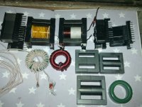
and 1 correction, the core is EE42 3c90 from feroxcube, I think that I can get 700-800w from that core.. when I make it work OK :(


I am not sure about the nature of the problem you are facing, please show me picture of your PCB

If you are using snubber at the MOSFETS, REMOVE THEM and repeat your test.

Your layout looks just OK for the first SMPS you build.

What is the supply voltage of your SG3525?
 

kaip

New member
Here my version.
I added some extra options to be able to use regulated as per standard design posted earlier in this thread by MicrosiM.
Protection board on PCB.
Please check and comment !

smps01_sch.jpg
smps01_top.jpg
smps01_brd.jpg
smps01_bot.jpg
 

MicrosiM

Administrator
Staff member
@ kaip


looks really nice

just make more space between the TOP cooper layer and the pins of the components. let say 2mm minimum


regards
 

kaip

New member
Thanks. Its my first SMPS.
I wanted to start with a known working design and I m happy with all the feedback you guys can give.

I used the soldermasks for the pads in the jpeg files.
Here are the actual top & bottom in PDF format. (scroll down a bit. Board is about 140x150mms)
All clearances are ok now. They appear to be different in PDF from real live gerber files.
There will be a solder mask so that will provide extra insulation anyway.
View attachment smps01_top.pdf
View attachment smps01_bot.pdf
 

kaip

New member
wally7856: If you just use it without the feedback as in this thread. The transformer (ratio between primary and secundary windings) define your output voltage. There is a calculator for this somewhere on this forum.

Output will be about +/- 50V with the transformer material and ratio shown (22 turns prim. / 16 sec.).

If you use the feedback you will have to do some more reading to figure out specific values.
Basic schematic based on this: View attachment smps_110_220vac_134.pdf as was posted earlier in this thread.

My schematic has all the components for both methods, just leave out what you do not need.
 

IGBT

Switching Fanatic!
Very good layout, I like the pcb

No, not really. I have ordered the trafo and some components to make sure I have the right sizes
before the PCB can be ordered.
They should be here tomorrow.

Will keep you updated.

Hey!!

Are you going to share the PCB design with us?


I will make one, but i need a working design as ludo didn't share the design with us :(


hope u help
 

kaip

New member
Hey!!
Are you going to share the PCB design with us?
I will make one, but i need a working design as ludo didn't share the design with us :(
hope u help


Here is my latest version. It is a bit smaller (about 14x12cm) it uses fewer but bigger sized elcos.
ULTIpost plot file3.jpg

I will share the gerber files when i have a working prototype.
Will also sell the PCBs to fellow enthusiasts.
 

irvynejay

New member
Cores

hello MicroSim now i finaly have the following core ETD49, ETD59,EE55,and T50 and litz wire measure 1.7mm
i am planning to make Ludo's smps using SG+2110 SMPSv3.11. i hope you can guide me ,ty
 

Attachments

  • DSC00913.JPG
    DSC00913.JPG
    295.6 KB · Views: 201
  • DSC00914.JPG
    DSC00914.JPG
    248.8 KB · Views: 172
  • DSC00915.JPG
    DSC00915.JPG
    264.3 KB · Views: 174
  • DSC00916.JPG
    DSC00916.JPG
    296.5 KB · Views: 201

irvynejay

New member
ill make pcb of ludo SG+2110 ver3.11 ill post it if i made it pls guide me ty
all parts is ready except mur1560 i can only get MUR3060ct and STPR1620
ang my aux trapo is 20volts ac could this work?

is the litz wire 1.7 mm ok?

one more thing what would you suggest to make Ver3.11 or 2.1 Sir MicroSim
 
Last edited:
Top