You are using an out of date browser. It may not display this or other websites correctly.
You should upgrade or use an alternative browser.
You should upgrade or use an alternative browser.
1.5 KW Class D amplifier based on IRS2092, Commercial
- Thread starter MicrosiM
- Start date
- Status
- Not open for further replies.
Good day Mr. Microsim, I am testing my own variant with IRS2092, can I inspire from your schematic ? Password missing. Thank you...
My schematic is almost the same one from the IR application note for IRS2092
Dimonis
New member
Can show you my applications of 2092
First : With dual mosfet IRFI4212 +/-35V power supply , oscilating freq. 400kHz , 4Ohm load , 10%THD at 150W , 0.03% at 100W, 0.006 at 1-50W.


Second : output mosfets are IRFB5615 +/-55V supply ,4Ohm , 350kHz ,max power - 320W ( 10%THD) , 1-100W - 0.02%THD.


First : With dual mosfet IRFI4212 +/-35V power supply , oscilating freq. 400kHz , 4Ohm load , 10%THD at 150W , 0.03% at 100W, 0.006 at 1-50W.
Second : output mosfets are IRFB5615 +/-55V supply ,4Ohm , 350kHz ,max power - 320W ( 10%THD) , 1-100W - 0.02%THD.
dudaindc
Analog Ears!
Can show you my applications of 2092
...
Nice job Dimonis! :UP:
Dimonis
New member
Didn't catch you , could you place some schematic on this subject?Nice job, I prefere to place on PCB good Sallen Key 4th order low pass filter, because original "RC filter" is not sufficient. 6dB/oct only...
I think that 4 order would be a problem at power after 100Watts.
Dimonis
New member
Thanks :adoration:Nice job Dimonis! :UP:
These PCB are for experiments only , to understand relation THD due to many factors.
tranbaobien
New member
hi all !
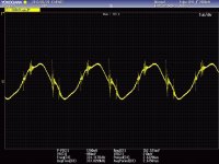
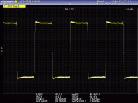
I am new in class d. i built irs2092 amps working base on amps-7d, +/- 50Vdc .fs~380 khz,
Rgate 15 ohms and 5819 , coil 22uh and .47uf/250v, with no input signal , but the output have some hi frequency noise.
Can anyone help me avoid the noise ?
I am new in class d. i built irs2092 amps working base on amps-7d, +/- 50Vdc .fs~380 khz,
Rgate 15 ohms and 5819 , coil 22uh and .47uf/250v, with no input signal , but the output have some hi frequency noise.
Can anyone help me avoid the noise ?
Attachments
-
 000.jpg174.5 KB · Views: 52
 -
 002.jpg171 KB · Views: 57
Hi Microsim, if is possible have the password for the schematic i have some time and would like to partecipate to this Class D project by making my version of the PCB, I have some experience with amplifiers and single, dual layer PCB.
Just for reference the pdf of two PCB I made, one is a board with 4 ch line mixer + 3 ch TDA amplifier (2 ch and 1 sub), the other is a 300w mono class AB amplifier.
I am sorry for the late response, I missed the post!
I don't know if you can make the PCB and test it, its double sided PCB
please let me know
repomessoni
New member
I am sorry for the late response, I missed the post!
I don't know if you can make the PCB and test it, its double sided PCB
please let me know
Hi Microsim, I have an old version of PCB CAD but work very well and 2 layer PCB is not a big issue, let me see the schematics and I will see how to move forward.
As soon will be ready a first version we can evaluate toghether before start to make the PCB.
I do some repair (for friends) of AV equipment (pro and home, SMPS included) and I have a dedicated bench with PC+EMU sound card+ few software, 50MHz Philips scope (quite old but still in well shape), DC dual power supply, 2.5kw variac, JBC soldering/desoldering station (for TH and SMD components), LG function generator, diy 8/4 ohm 2x1kw resistive dummy load.
With my tools I think will be not a problem make the PCB and test it, of course will take time, depend on complexity and what parts of this schematic can be excluded because not really important for a diyers projetc.
Last edited:
Could you send me the password by email: m.chaurais@ymail.com?
thank you very much.
thank you very much.
Check PM,
thanks
thanks for the reply.
I have some experience with the class ab.
while the Class D are a beginner, I'm learning slowly, even with your help thanks
- Status
- Not open for further replies.