You are using an out of date browser. It may not display this or other websites correctly.
You should upgrade or use an alternative browser.
You should upgrade or use an alternative browser.
1kW smps project (based on MicrosiM design)
- Thread starter ludo3232
- Start date


Michelle, is this work in progress or a finished design? I was trying to find the source of the CPR signal on the main schematic but can not find any current sensor. I do not see any voltage feedback either. Also how many watts is this supply designed for and has it been tested.
Hi Wally
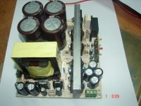
greetings this is a 2.6kw smps made by hien i have not personally made it so i cant comment but its very similar to what i have made in #722 the first picture only my smps has no protection i
have made pcb for 3 pairs IRFP260 with EE65 CORE its tested and working so i am designing new pcb with protection for 15 volts dc supply i used VIPER22A but TOP244 15volts supply gave a better result
so maybe i have to make small trafo for top244 15 volts supply
warm regards
michelle
Thanks michelle, i took a look at the schematic over there. I see he has current sensing resistors on each FET tied together to measure current. I think those 2 points must be summed together to get a true current reading. This looks to me like a good power supply to use a current transformer on.
For RC snubbers,5R6/2W and 330 pf/500v as a starting point, what do you think?
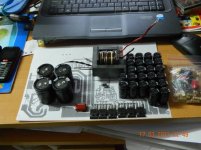
hi sir i want to know that in 1kv smps based on microsim design using ir 2110& sg3525 &etd 49 core the wattage is 1kv. if i change the mosfet irfp460 to igdt g4pc50u the supply can go to how many watts.should it will remain the same or the wattage will increase so tell me its max watt using igbt g4pc50uwhile replacing the old rectifier with the larger one, the pcb got a little bigger, but that will be corrected. also the current sense lines are a piece of cable (like ludo's prototype), thinking about moving the ne555 from the protection circuit a little higher (then you have to use cable). have to add the ultra-fast diodes and caps, and move the ETD core more to the right. if you spot some mistakes, please say right away.

My project was retarded by laws of nature. The world was not prepared for it. It was too far ahead of time. But the same laws will prevail in the end and make it a triumphal success.
Hi Exflaco
greetings friend this smps be finished soon i will post full pcb schematic for you and all diyers its working but on new pcb have to test
warm regards
michelle
Hi Exflaco
greetings friend this smps be finished soon i will post full pcb schematic for you and all diyers its working but on new pcb have to test
warm regards
michelle

Hi.
I try to choose the snubber.I do not know how to choose the resistors.
course without capacitor, Dren/Source Q1 (osciloskope 10V/plot,probe 10X)
http://imageshack.us/photo/my-images/42/przedbj.jpg/
I used a capacitor 4,7nF
http://imageshack.us/photo/my-images/20/92644902.jpg/
I try to choose the snubber.I do not know how to choose the resistors.
course without capacitor, Dren/Source Q1 (osciloskope 10V/plot,probe 10X)
http://imageshack.us/photo/my-images/42/przedbj.jpg/
I used a capacitor 4,7nF
http://imageshack.us/photo/my-images/20/92644902.jpg/
Hi.
I try to choose the snubber.I do not know how to choose the resistors.
course without capacitor, Dren/Source Q1 (osciloskope 10V/plot,probe 10X)
I used a capacitor 4,7nF
Please UPLOAD your images to the forums directly, this will way they will still available.
show me picture of your setup please, becasue i cannot access those links


I bought a new digital oscilloscope. Now I will do a professional measurements.
Thats very good, I recommend that you re post the waves. and some pictures of your setup.
tebci
New member
Thank youuuuuuuuuuuuuuuuuuuuuuuuuuuuuuuuuuuuuuuu King
??? for what is this
Thank youuuuuuuuuuuuuuuuuuuuuuuuuuuuuuuuuuuuuuuu King
hi alian pls post pictures