You are using an out of date browser. It may not display this or other websites correctly.
You should upgrade or use an alternative browser.
You should upgrade or use an alternative browser.
2 kwts discreet class d need help
- Thread starter stewin
- Start date
yes u can use it, but i already test with 2 above is enough. Unless if u face aux transistor hot or not enough current then u can add more like earlier post. Im nearly finish new board, now i just need to mount component on the board. I`m plan to make 2 module, 1 st module has been success without totem pole and another is coming with totem pole, and im plan to order pcb from manufacturer for both if success using smd component, this is not a promise but planning  . since this amp produce very nice sound, clear and high fidelity amp, i think thats why hypex success on their business. I got it work nicely and loud without add op-amp. Minimum inductance with my test about 12 uh and its still survive. lower the inductance will increase ampere at output but watching mosfet stress too because not all mosfet can drive at lower inductance will cause heat a little and if improper bias + gate setting will cause blown ur mosfet too, but in my case none mosfet blown yet . I think tomorrow i`ll finish second module for the totem pole version with new board.
regards.
. since this amp produce very nice sound, clear and high fidelity amp, i think thats why hypex success on their business. I got it work nicely and loud without add op-amp. Minimum inductance with my test about 12 uh and its still survive. lower the inductance will increase ampere at output but watching mosfet stress too because not all mosfet can drive at lower inductance will cause heat a little and if improper bias + gate setting will cause blown ur mosfet too, but in my case none mosfet blown yet . I think tomorrow i`ll finish second module for the totem pole version with new board.regards.
protection, OVP, UVP and OTP.
here is the schema for the protection, there is no SD pin in discrete ucd schema. So to enable this protection u need to disconnect R3 from ground and connect this SD pin as i mention in this schema to R3 and its done.
D1 is for zener diode to set maximum voltage for ur amp and D2 is setting minimum voltage for ur amp.
regards
here is the schema for the protection, there is no SD pin in discrete ucd schema. So to enable this protection u need to disconnect R3 from ground and connect this SD pin as i mention in this schema to R3 and its done
. D1 is for zener diode to set maximum voltage for ur amp and D2 is setting minimum voltage for ur amp.
regards
Attachments
Looks at this video I`m success running amp with totem pole 4 pcs mosfet and still halfbridge. There is no need full bridge for this model, lots of improvement such as THD and fidelity. Core i use is EI33 taken from old computer psu, wound it with AWG 17 coil and measure it about 25 uH. dc offset only 10mv. There is some additional part i need to mount at pcb but i just ignore it for a while because i want to test this amp fast. Later i`ll add full component on it, OVP, UVP, OTP and OCP. protection board is ready and finish, but i need to power it up first lets see there is something blown or not, Unfortunately they run smooth and powerfull at first time power up. . so tomorrow i`ll put all protection on the board, for now i just made 2 models, first is only use 1 pair mosfet standard discrete ucd style, and second this one which run 2 pair of mosfet.
all prototype usually i`ll put it with care at some place, its for future referrer design.
so the result:
no overheat, no noise, no pop at start up, no pop at power off. more power, thd improve, clear sound.
regards.
[video=youtube;_qrD2Q1MGgo]http://www.youtube.com/watch?v=_qrD2Q1MGgo[/video]
I`m success running amp with totem pole 4 pcs mosfet and still halfbridge. There is no need full bridge for this model, lots of improvement such as THD and fidelity. Core i use is EI33 taken from old computer psu, wound it with AWG 17 coil and measure it about 25 uH. dc offset only 10mv. There is some additional part i need to mount at pcb but i just ignore it for a while because i want to test this amp fast. Later i`ll add full component on it, OVP, UVP, OTP and OCP. protection board is ready and finish, but i need to power it up first lets see there is something blown or not, Unfortunately they run smooth and powerfull at first time power up. . so tomorrow i`ll put all protection on the board, for now i just made 2 models, first is only use 1 pair mosfet standard discrete ucd style, and second this one which run 2 pair of mosfet.all prototype usually i`ll put it with care at some place, its for future referrer design.
so the result:
no overheat, no noise, no pop at start up, no pop at power off. more power, thd improve, clear sound.
regards.
[video=youtube;_qrD2Q1MGgo]http://www.youtube.com/watch?v=_qrD2Q1MGgo[/video]
Last edited:
Stewin 2 pairs IRF640N is possible with +/- 60 vdc, re-adjust gate resistor and duty cycle. For subs IRFP250N 1 pair is enough or u want it play hard at 2 ohm u should add another pair and re-adjust LC filter too.
2 pairs irf640N with +/- 60 vdc, u need 22uH and 1uf filter caps. gate can maintain at 27 ohm. totem pole gate 4.7 ohm should be fine too.
2 pairs irf640N with +/- 60 vdc, u need 22uH and 1uf filter caps. gate can maintain at 27 ohm. totem pole gate 4.7 ohm should be fine too.
UPDATE: after few modification was made then i get dc offset only 0.001 vdc, which means 1mv, even i increase duty cycle there is no heat at mosfet , cool huh? i`m almost didnt hear any distortion at full volume, there is lots different with 1 pair, but still 1 pair can play loud enough.
So i`m finish here, i hope stewin can archive it too, then after success u can go with 2kwrms even more !!! Trust me, and i`m done here with stewin mission, btw stewin u need to do what i do if u want to fits ur need.
regards.
Azmi
So i`m finish here, i hope stewin can archive it too, then after success u can go with 2kwrms even more !!!
Trust me, and i`m done here with stewin mission, btw stewin u need to do what i do if u want to fits ur need.regards.
Azmi
Nice work
UPDATE: after few modification was made then i get dc offset only 0.001 vdc, which means 1mv, even i increase duty cycle there is no heat at mosfet , cool huh? i`m almost didnt hear any distortion at full volume, there is lots different with 1 pair, but still 1 pair can play loud enough.
So i`m finish here, i hope stewin can archive it too, then after success u can go with 2kwrms even more !!! Trust me, and i`m done here with stewin mission, btw stewin u need to do what i do if u want to fits ur need.
regards.
Azmi
Hi Norazmi
greetings nice vedio the you tube one just want to ask you power of amp you posted on you tube and at what supply voltage can it be used in full bridged mode is it safe if possible can
you post close up picture of your pcb so i can see component so i can design pcb any replacement for
BAT45 diodes norazmi you really have worked HARD on this project THANKS
warm regards
michelle
Michelle the video i posted on youtube is halfbridge not fullbridge. Yes halfbridge with 4 pcs mosfet means 2 pair, full bridge could be 8 pcs (4 pair) lol, we can even do parallel 3 or 4 pairs with this setup with only halfbridge mode, but take note that parallel more mosfet need to have big power supply to feed mosfet. Not enough current at supply rails will cause ucd amp distort at high volume and voltage drop too much. Supply rails can be +/-35 to +/- 90 with care. depends on what output mosfet u use, IRFP250N can go up to +/-75 with 2 pair.
Btw full bridge is possible and nothing to worried except u need proper protection for OTP, UVP, OVP and OCP. I dont do full bridge its too loud and i dont have place to play with it. I will take closer picture soon. For the shcottky diode there is alot of replacement see below:
higher recommended :
BAT54
BAT64
SB160
1N5819
etc..
Medium Recommended:
MUR120
UF4004
etc...
Lower Recommended:
1N4148
etc...
any slow diode such as 1N4007 and so on CANNOT be used with ucd, its NOT permitted and totally wrong replacement at all so dont try it
lol, we can even do parallel 3 or 4 pairs with this setup with only halfbridge mode, but take note that parallel more mosfet need to have big power supply to feed mosfet. Not enough current at supply rails will cause ucd amp distort at high volume and voltage drop too much. Supply rails can be +/-35 to +/- 90 with care. depends on what output mosfet u use, IRFP250N can go up to +/-75 with 2 pair.Btw full bridge is possible and nothing to worried except u need proper protection for OTP, UVP, OVP and OCP. I dont do full bridge its too loud and i dont have place to play with it. I will take closer picture soon. For the shcottky diode there is alot of replacement see below:
higher recommended :
BAT54
BAT64
SB160
1N5819
etc..
Medium Recommended:
MUR120
UF4004
etc...
Lower Recommended:
1N4148
etc...
any slow diode such as 1N4007 and so on CANNOT be used with ucd, its NOT permitted and totally wrong replacement at all so dont try it
hi nozrami thanks a lot for your support:UP: . here is schematic completed to the simulation you've done. now to the PCB arrangement. As a professional please advice for minimal noise which, components should not be placed near each other;ww:;ww:. I'm using a double sided board in order to use the top side as the ground plane of which i think it will help arrest straying hf noises, therefore improve the noise reduction.
. here is schematic completed to the simulation you've done. now to the PCB arrangement. As a professional please advice for minimal noise which, components should not be placed near each other;ww:;ww:. I'm using a double sided board in order to use the top side as the ground plane of which i think it will help arrest straying hf noises, therefore improve the noise reduction.Attachments
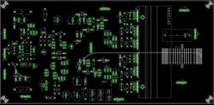
Stewin, your schema above is very good. To avoid noise and hf freq, feedback should be short as possible, the feedback trackmust be take care, as u can see my ucd pcb, i put LC filter at the middle on pcb because i want to make feedback as close as possible and less track. Stewin 3.3k 2 watts dummy load really need at output after LC filter to GND it will make ucd amp oscillate very well. If there is no mistake while u assembly this new pcb, this amp should work well and i think your feedback too should be ok and if u still have noise tell me and i`ll try to guide u to remove the noise totally because i dont have noise problem with discrete ucd even my pcb is ugly and little big. The advantage of using totem pole is power mosfet will not heat or stress even u increase duty cycle at optimum setting. and buffer totem pole transistor driver gate need enough current to drive it. so 2 seperate aux seems to be compromise here and will do good job.
Op amp supply also nice with only resistor clamp with 12v or even 15v zener diode. Noted that because the output will have double current when we do parallel the mosfet so we really need good output filter coil (inductor) and big coil such as minimum awg18 to awg 17, make it tight possible when winding or even use glue on it to avoid ringing when play at high volume to avoid vibrating. with EI core i make 5mm gaps and if u use T106-2 there is no worry about gap. but both will work ok and nicely.
regards.