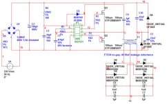
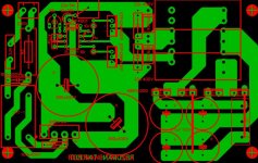
Attached there are the schematic and layout. If you are interested I can export the layers separate, or send the sprint-layout file.
The core should be ETD34, N87/N97 material or equivalent. Primary turns should be 25 turns (I use 4 times 0,4mm diameter), and secondary should be half-overlapped with primatry to get correct leakage inductance (40-50uH). Secondary is on your output voltage needs (Uout=n/25*160, where n is number of turns for secondary). Secondary should be wound with stranded wire, with proper copper-area.
FETs should be: IRF740 (cheap, but old, can be get everywhere, moderate cooling needed), STP12NM50FP (my preferate, good fet), or any other rated for at least 8A (current at short circuit limited to this, by resonant elements), with low RDSon, and LOW GATE CHARGE (most important, should be under 50nC).
I tested this supply (with older layout) with bulbs, power resistors and amplifiers. It worked pretty well. If you need less voltage drop you should increase resonant caps to 33n and decrease leakage inductance to 30uF, but then you need FETs rated for 12A (and more cooling), and better diodes than UF5404 (these are 3A 400V ultrafast diodes, you will need fast high-voltage diodes with 5A rated current at least, like some MURs)
Switching freq should be adjusted to your resonat cap / leakage inductance values (about 110kHz)
This schematic can provide 500W with the following changes:
- better FETS, for example some STP20NM50 FETs should get 500W with moderate cooling
- output diodes should heatsinked effectively
- transformer is wound with optimal stranded wire, up to its maximal winding area.
- resonant caps 33n, leakage inductance 26uF
- swithcing freq is 120kHz
IR2153 can be used, but it has more dead-time. So you should encounter more voltage drop at loaded conditions.
All safety issues should be well understood by builder before building!
")