800W Half Bridge SMPS for audio amplifier

giololucas

New member
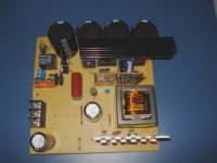
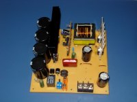
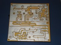
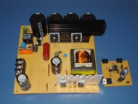
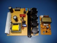
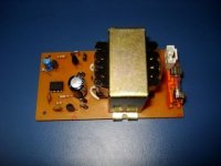
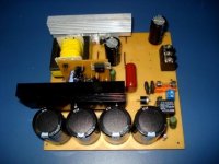
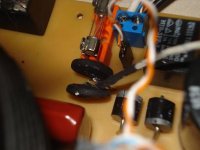
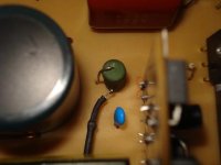
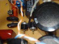
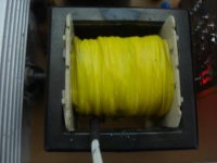
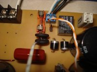
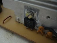
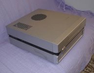
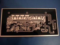
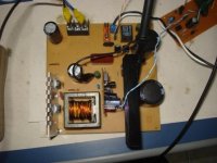
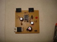
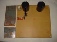
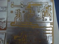
My second prototype SMPS based in many others in this site.
Special thanks to microsim, zeus and ludo for sharing knowledge for free, this is a noble atitude.
Their help and knowledge were fundamental to my sucess in this prototype. :UP:

For a while 1st test
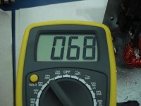
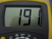
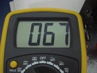
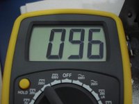
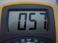
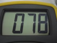
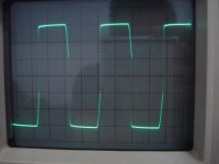
-30 minutes unloaded: result = Ok :UP:
Soft-start working ok, no heat in any part

Working with half of caps in mains and secondary, have to wait saturday to buy more...:(

See photos attach .
Enjoy it
More soon...
 

Attachments

  • DSC05310.JPG
    DSC05310.JPG
    33.9 KB · Views: 1,623
  • DSC05308.JPG
    DSC05308.JPG
    25.7 KB · Views: 1,043
  • DSC05314.JPG
    DSC05314.JPG
    22.7 KB · Views: 750
  • DSC05299.JPG
    DSC05299.JPG
    24.9 KB · Views: 739
  • DSC05304.JPG
    DSC05304.JPG
    33.1 KB · Views: 875

giololucas

New member
Soft Start movie

Movie shows soft start action across primary terminals

[video=youtube;L6kSVm11vlM]http://www.youtube.com/watch?v=L6kSVm11vlM[/video]
 

giololucas

New member
600W test pass !

Movie shows second test.

630W everything ok and no heat , with forced cooling.


[video=youtube;3fwkMy8n0Iw]http://www.youtube.com/watch?v=3fwkMy8n0Iw[/video]


Enjoy it
 

giololucas

New member
830W survived!

Just put 830W load and it survived for 2 minutes, 88,5 VCC 9,8 Amps, 2 volts of Ripple, What a good result:UP:!
To run a longer test I will replace the small heatsink in MURs for a bigger one.
In future I will order MURs 820 to replace MURs 860, this will reduce heat in rectfiers also.

Now some decent pictures.
Take a look in mains caps, now complete 4 x 1000u 200V.
Other point, I had to install another termistor in parallel with the original one because I don´t have one for 10 Amps.

Enjoy it, and inspire yourself, with some effort and help of skilled members of this forum, it´s possible to do a working SMPS.
 

Attachments

  • assy1.JPG
    assy1.JPG
    74.7 KB · Views: 988
  • assy3.JPG
    assy3.JPG
    78.7 KB · Views: 734
  • bottom.JPG
    bottom.JPG
    78 KB · Views: 714
  • assy2.JPG
    assy2.JPG
    72.1 KB · Views: 819

MicrosiM

Administrator
Staff member
I am really happy for your success into your SMPS, with robust results as a start.


let me know core you are using, I think you need a slight adjustments of turns, its clear from primary wave.

if you use LITZ wire into your transformer, you will get the ultimate power

If you show wave across mosfets, will be very good also :UP:

Good luck :UP:
 

giololucas

New member
I am really happy for your success into your SMPS, with robust results as a start.


let me know core you are using, I think you need a slight adjustments of turns, its clear from primary wave.

if you use LITZ wire into your transformer, you will get the ultimate power

If you show wave across mosfets, will be very good also :UP:

Good luck :UP:

Hi Microsim. Thanks for reply.
Core used is this one in attached, cross section is 2.4mm2. Supplier says that it´s similar to ETD49.
For sure I need a fine tune, as I said in the video that spike it´s not very good... :(
Just don´t know how to do it exactly.

The way I used to wind it was the most ugly one:
1st all primary: 2 wires of 0.7mm diameter.
2nd: wind All secondary in the same direction of primary , 2 wires of 1.6mm diameter.
 

Attachments

  • material.pdf
    114 KB · Views: 2,237

giololucas

New member
Last Mods and 850W test sucessfull

After mods described below, runned 2 minutes at 850W load (9,5Amps x 85,5V)

-Transformer rewinded with 4x 0,72mm dia primary 13 turns
-Switching increased from 52kHz to 63kHz.
-Replaced heatsink of sec diodes for a bigger one
-Max flux swing: 1600 Gauss (calculated)

Results without fan, 2 minutes of load.
-Mosfets: 40ºC ok
-Transformer : 40ºC ok
-Mains diodes: 65ºC !!!: no good
-Mains termistor 65ºC !!!: no good
-Secondary Diodes 55ºC ok
-Snubber resistor: 55º ok

Enjoy it.
 

Attachments

  • finish1.JPG
    finish1.JPG
    22.5 KB · Views: 901
  • aux finish.JPG
    aux finish.JPG
    20.2 KB · Views: 608

MicrosiM

Administrator
Staff member
After mods described below, runned 2 minutes at 850W load (9,5Amps x 85,5V)

-Transformer rewinded with 4x 0,72mm dia primary 13 turns
-Switching increased from 52kHz to 63kHz.
-Replaced heatsink of sec diodes for a bigger one
-Max flux swing: 1600 Gauss (calculated)

Results without fan, 2 minutes of load.
-Mosfets: 40ºC ok
-Transformer : 40ºC ok
-Mains diodes: 65ºC !!!: no good
-Mains termistor 65ºC !!!: no good
-Secondary Diodes 55ºC ok
-Snubber resistor: 55º ok

Enjoy it.


I am really glad for your success.


Its normal to hit 65C with your test


My SMPS used to hit 90 ~ 110 C without fan for testing purposes (using original parts).

With fan above rated load used to hit 75C.

with Small Heat sinks, see my project in forum

You have to short your NTC using a relay at this load


Good luck
 

giololucas

New member
I am really glad for your success.


Its normal to hit 65C with your test


My SMPS used to hit 90 ~ 110 C without fan for testing purposes (using original parts).

With fan above rated load used to hit 75C.

with Small Heat sinks, see my project in forum

You have to short your NTC using a relay at this load


Good luck

Hi microsim.
Thank you for response.
I´m afraid to burn mains diodes, if it short mains ac will flow on mains cap. creating risk of explosion. As you always say, and I totally agree with you - "SMPS don´t joke, they are really bad"
I´m thinking in replace this 600V x 10amps mains diodes (the 2 cylindrical blacks near to relay) to a 15 amps x 400V TO-220 diodes with small heatsinks.
About NTCs I feel ok for a while, if it destroy it´s ok, no big damage.
 

Attachments

  • finish2.JPG
    finish2.JPG
    24.5 KB · Views: 392

MicrosiM

Administrator
Staff member
Yes, stay on the safe side, while you dont have protection circuits yet, play safe! and use fans!

SMPS dont joke when they e fail!

Good Luck!
 

giololucas

New member
Temperature tests no load and wiht 830W load

Hi everybody.
Here are some pics of temperature measurements.(all results are in celsius degrees)
I´m just posting the hotter points of smps, critical ones. If someone want to know other points please ask me.

Pics named no load were taken after 1 hour (time to reach temp stabilization)

Pics named with load were taken
-after 15 minutes temperature got stable with 830W to 850W load and ligth fan (PC smps cooler powered with 5Volts)

Room temp was about 23ºC with none ventiltation (door and windows closed)

One important point is the thermistor temp. it´s almost 200ºC with load and none fanning! :x:
 

Attachments

  • temp secondary diodes with load no fan.JPG
    temp secondary diodes with load no fan.JPG
    33 KB · Views: 61
  • measuring point thermistor with fan and with load.JPG
    measuring point thermistor with fan and with load.JPG
    32.6 KB · Views: 99
  • measuring point snubber resistor no load and no fan.JPG
    measuring point snubber resistor no load and no fan.JPG
    25.4 KB · Views: 77
  • measuring point primary diodes with load no fan.JPG
    measuring point primary diodes with load no fan.JPG
    32.1 KB · Views: 72
  • temp thermistor no fan with load.JPG
    temp thermistor no fan with load.JPG
    24.4 KB · Views: 64
  • measuring point Transformer no fan.JPG
    measuring point Transformer no fan.JPG
    27.1 KB · Views: 84
  • measuring point thermistor no fan with load.JPG
    measuring point thermistor no fan with load.JPG
    35.6 KB · Views: 78
  • temp primary diodes with load no fan.JPG
    temp primary diodes with load no fan.JPG
    29.6 KB · Views: 56
  • measuring point secondary diodes with load with fan.JPG
    measuring point secondary diodes with load with fan.JPG
    25.1 KB · Views: 62
  • temp thermistor with fan and with load.JPG
    temp thermistor with fan and with load.JPG
    30.6 KB · Views: 53
  • temp transformer no load and no fan.JPG
    temp transformer no load and no fan.JPG
    25.8 KB · Views: 45
  • temp snubber resistor no load and no fan.JPG
    temp snubber resistor no load and no fan.JPG
    22.9 KB · Views: 38
Hi giololucas am just going through your thread haven't had time to be around here these days. Great results keep it up congrats.
 

giololucas

New member
Hi giololucas am just going through your thread haven't had time to be around here these days. Great results keep it up congrats.

Thank You Zeus.
Now I bougth a big box to install my power amplifier and SMPS.
See one pic in attach. This amp will be posted in another thread.
It will be repainted in black and will have a 8 band spectrum analyzer.
 

Attachments

  • amplifier case.JPG
    amplifier case.JPG
    15.9 KB · Views: 137

giololucas

New member
This is the board for my new amp.
It´s a JBL 300W rms based.
I built 5 of these I like this amp very much.
Enjoy it.
 

Attachments

  • Amplifier board.JPG
    Amplifier board.JPG
    36.7 KB · Views: 573

michelle

New member
pcb

Hi giololucas
greetings nice sub pcb will you share pcb what output transistors you use in this sub amp
warm regard
michelle
 

giololucas

New member
Hi giololucas
greetings nice sub pcb will you share pcb what output transistors you use in this sub amp
warm regard
michelle

Hi michelle I used tip 35 and tip 36, like in original JBL design.
The sound is very clear and soft with very good sub response and attack.
I will use it to drive stereo speakers (klipsch or JBL I didn´t decided yet).

Regards
 
Hi giololucas great those micro component system already have back holes thatyou won't have to drill. Glad to see your project is moving ahead. Good luck. question besides soft start at start up with your Ne555 + relay, do you short your caps with bleeder tresistor when the smps switches off? Thanks
 
Last edited:

giololucas

New member
Hi giololucas great those micro component system already have back holes thatyou won't have to drill. Glad to see your project is moving ahead. Good luck. question besides soft start at start up with your Ne555 + relay, do you short your caps with bleeder tresistor when the smps switches off? Thanks

Hi zeus!
Sorry for late response, I´m working a lot these days, and all projects are stopped again:(.
SMPS doesn´t short caps when it turn off. There are direct 47K bleeder resistors connected to caps all time.

Best Regards.
 
Top