You are using an out of date browser. It may not display this or other websites correctly.
You should upgrade or use an alternative browser.
You should upgrade or use an alternative browser.
Another IR2153 smps
- Thread starter borysgo2
- Start date
Jagd.Panther
New member
The core is coated with black plastic. I was checking it up to 5A peak current and it was not saturating (didnt look like).
Should I make another one with green core larger in size ??
Thanks
If it works for you then why bother?
Jagd.Panther
New member
I'm kind of lost. 5v line is not a winding on the magmap, it's wound on separate core, it's merely a source of AC (all magamps work on AC).the 5v line is one winding on the mag amp and the control line is the second. He only had one winding so it had to be an inductor.
The control line is a line, not a winding. It's used to reset the magamp core to control the point where the core saturates (and becomes virtually a shor)t. All that is realized with just one winding.
So we have a magamp with one multi-duty winding based on saturable reactor.

Jagd.Panther
New member
please post a pic of the pcb you use
I update this circuit but all mosfet still is died.
I try to test the IR2153 using LED and resistor with change Rt (2M) and Ct (47nf) the frequency aprox 7Hz and all LED lights FLIP-FLOP.
Please advice.
I try to test the IR2153 using LED and resistor with change Rt (2M) and Ct (47nf) the frequency aprox 7Hz and all LED lights FLIP-FLOP.
Please advice.
Attachments
-
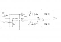 IR2153_SMPS2.jpg58.1 KB · Views: 153
 -
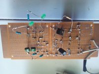 IR2153_SMPS2_pcb.jpg66.4 KB · Views: 126
 -
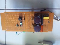 IR2153_SMPS2_pcb1.jpg47.9 KB · Views: 87
Last edited:
lynxlynx
A rumbling soft motor
I update this circuit but all mosfet still is died.
I try to test the IR2153 using LED and resistor with change Rt (2M) and Ct (47nf) the frequency aprox 7Hz and all LED lights FLIP-FLOP.
Please advice.View attachment 5549
Try to add 1k resistors from gate to source of each half bridge MOSFET
Jagd.Panther
New member
For operation over 30khz, C1 (C2 on previous schematic) => 0.2-1uF (low ESL, e.g. ceramic), C3 (C6 on previous schematic) => 0.1-0.47 uF (low ESL, e.g. ceramic). Place caps as close to Ir2153 as possible. Do you have a picture of the PCB you used when you have mosfets installed?I update this circuit but all mosfet still is died.
I try to test the IR2153 using LED and resistor with change Rt (2M) and Ct (47nf) the frequency aprox 7Hz and all LED lights FLIP-FLOP.
Thank You for your replay.
Ok, next I will attc picture of the PCB with mosfet installed.
I had updated this schema and the mosfets not die again.
But light of the lamp is very poor and all the mosfet is very hot.
When I measure pin 1 Vcc (IR2153) to ground is 14.8 volt.
But when I measure pin 7 to pin 6 the voltage is 4.8volt and pin 5 to ground the voltage is 5.5volt.
And when I measure between plus and minus source, the voltage is 60volt (before it is 310volt)
Please help. (I'm sorry my english is not good)
Thank You.
lynxlynx
A rumbling soft motor
Thank You for your replay.
Ok, next I will attc picture of the PCB with mosfet installed.
I had updated this schema and the mosfets not die again.
But light of the lamp is very poor and all the mosfet is very hot.
When I measure pin 1 Vcc (IR2153) to ground is 14.8 volt.
But when I measure pin 7 to pin 6 the voltage is 4.8volt and pin 5 to ground the voltage is 5.5volt.
And when I measure between plus and minus source, the voltage is 60volt (before it is 310volt)
Please help. (I'm sorry my english is not good)
Thank You.
View attachment 5567
If you're measuring with regular multimeter then it's fine, such measurements show only average voltage if IR2153 outputs with almost full 50% duty. If you have your fets heating then you need to check the gate waveform somehow (with oscilloscope)...

lynxlynx
A rumbling soft motor
Here is the picture mosfets installed.
The lamp's light still poor and mosfet very-very hot.
View attachment 5568
Thank You for your replay.
Ok, next I will attc picture of the PCB with mosfet installed.
I had updated this schema and the mosfets not die again.
But light of the lamp is very poor and all the mosfet is very hot.
When I measure pin 1 Vcc (IR2153) to ground is 14.8 volt.
But when I measure pin 7 to pin 6 the voltage is 4.8volt and pin 5 to ground the voltage is 5.5volt.
And when I measure between plus and minus source, the voltage is 60volt (before it is 310volt)
Please help. (I'm sorry my english is not good)
Thank You.
View attachment 5567
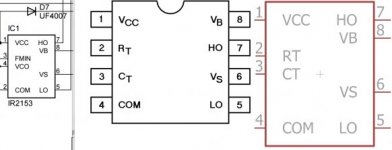
Also try to measure not pin7 to pin6, but high gate to pin6 and not pin5 to gnd but low gate to gnd (or measure voltage across gate resistor). Maybe you'd just picked up wrong part.
To avoid loosing mosfets I would attach a small heatsink to them (with insulation pads of course).
Last edited:
res_smps
Member
Here is the picture mosfets installed.
The lamp's light still poor and mosfet very-very hot.
View attachment 5568
1. your chip marking different from datasheet, i am not sure if it is genuine
2. lamp will not light brightly compared with directly connected to 220 line, because violtage at the lamp only 155v square wave (77v average or less measured with voktmeter)
Jagd.Panther
New member
Here is the picture mosfets installed.
The lamp's light still poor and mosfet very-very hot.
View attachment 5568
Can you please attach picture of the bottom side? Do you have an oscilloscope?
anyway, if you are using IRF740 and the switching frequency ~50 kHz, I suggest you to increase gate resistor to 50-100 ohm. BTW Did you install ceramic caps like I mentioned?
Also if you have installed 1k resistors across the gate-source, changed them to 10k or so.
Jagd.Panther
New member
Square wave 150V peak-to-peak, 0.9 duty cycle equals 135V RMS.2. lamp will not light brightly compared with directly connected to 220 line, because violtage at the lamp only 155v square wave (77v average or less measured with voktmeter)
res_smps
Member
Square wave 150V peak-to-peak, 0.9 duty cycle equals 135V RMS.
i think we made a mistake, it is 300vpp with duty cyle<50%

Can you please attach picture of the bottom side? Do you have an oscilloscope?
anyway, if you are using IRF740 and the switching frequency ~50 kHz, I suggest you to increase gate resistor to 50-100 ohm. BTW Did you install ceramic caps like I mentioned?
Also if you have installed 1k resistors across the gate-source, changed them to 10k or so.
Thank you for your replay.
Here is picture of bottom side and when this driver circuite running.
Unfortunately I still do not have an oscilloscope.
Now I am using IRF840 (after try to use IRF740 with the same result) with 10 ohm resistor on the gate.
Yes, I installed ceramic capasitor for Ct (IR2153).
And between gate-source I installed 10K resistor.


I have done some further work on the protection with IR2153, I think I know why so often it just sucks. If you are using open collector transistor or triac or mosfet to pull down Ct pin to GND make sure it is done very quick, otherwise your mosfets will be gone for sure. While pulling the Ct pin to GND the width of the ON/OFF ratio is changed and the frequency is changed too. So if you are just at about max load (let me say 5%) and you increase the load a further bit Ct pin might be not fully pulled down.
The IR2153 have UV detection and small mosfet build in, I have tryed to pull down Vcc voltage and it works perfect. So from practical point of view it is way easier to use Vcc pull down instead Ct pull down.
Hopefully it will help a bit.
Regards

The IR2153 have UV detection and small mosfet build in, I have tryed to pull down Vcc voltage and it works perfect. So from practical point of view it is way easier to use Vcc pull down instead Ct pull down.
Hopefully it will help a bit.
Regards
Small update.
I have removed the current sense trafo and used instead capactive divider, it works perfect. The SMPS is very quiet at over load (no buzzz or hiss noises), the setup is dead simple and works perfect. The dynamics of the protection can be easily seated up with a few capacitors.

I have removed the current sense trafo and used instead capactive divider, it works perfect. The SMPS is very quiet at over load (no buzzz or hiss noises), the setup is dead simple and works perfect. The dynamics of the protection can be easily seated up with a few capacitors.