Cloning Chinese SMPS and changing output Voltage.Need advice!!!

noz-25

LEDadict
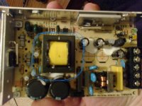
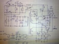
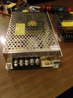
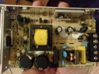
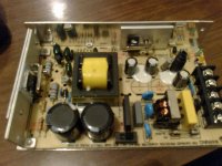
I buy this SMPS from chinese company becouse i need it for some project with LED.It is 24V 3,2A output.It has small potentiometer to change output voltage +-10%,which is very good think for me when i conect LED in series.When i open this SMPS a was very suprised how simple is it!Becouse i was very satisfied with it,i decide to clone it!I make revers ing. and draw shematic.I love to make SMPS with transistors becouse i have a diferent type of trans. so i can use it in best way for me.Power supply are very important to me becouse i am work with LED and always need some.My expirience with SMPS is 2 pcs work well and about 7-8 explosions!Hahaha.I don't have osciloskope but i work on it.I read MicrosiM topic about SMPS and take it very serious.
OK,what i need:I would like to rise up voltage to at least 48Volt!I am not yet apart transformer to se how it is make but i will do soon.My plan is to put him in the oven on 200 C' to melt glue and then split core,count turns....I do it before but if You have some better idea-i am listening.(MicrosiM i read Your post about transformer calculation but maybe it is better to apart him to see how isolation is build and what go first prim,or sec or feedback....)One think is confused me.It will be easy to just se how many volt give one turn and then to wind desired turns to get 48v.Rise up value of capacitor.But what hapens with optocapler?Will change of voltage fu*k up him?Is it just same for him does secundar give 24V or 48V?And for TL431?Here i expect ALL YOUR HELP COLLEAGUES!!!!Also i don't know what is topology of SMPS used here.If somebady have some expirience with similar type of SMPS,share Your expirience with me!!!I want to order some el. parts for SMPS.For my needs I need power supplyes with voltage around 24-60V and not more than 2-3A.I am sure You have some good but not to complicate shematics for me.Some trusted,tested SMPS.As i say SMPS is new for me-but electronic isn't!I make a lot diferent project in my life and electronic is something what i really love hole my life,since i was a kid.If i don't know something i am ready to study and learn.I will realy appreciate every given help!!!Here is the picture::w)
Fotografija0196.jpgFotografija0200.jpgFotografija0201.jpgFotografija020011.JPGFotografija0207.jpg

I will draw the shematic in some program,but for now this is it!
 

noz-25

LEDadict
Is it possible that nobady want to coment this?I really need help about voltage increase-is it problem becouse of optocoupler and tl 431?Thank You
 

MicrosiM

Administrator
Staff member
You can increase the voltage of the SMPS output to 48V by increasing the number of turns of the secondary side.

Taking the transformer a part wont be easy task, and you may crash it.

I advice that you buy a ready SMPS 48V for your application.

I cannot comment on the feedback circuit, if it will work with the 48V or not

You need to increase the voltage for the secondary capacitors.

Regards
 

noz-25

LEDadict
;ww:You know MicrosiM...i wasn't suprised when from one other "electronic-forum" get advice "It is easier to buy another power supply :)",but when i now read message from YOU "advice me to BUY 48V SMPS" I REALY CAN NOT BELIVE!!!It's seems this site is not (and YOU ARE NOT) what it represent that is!Maybe You are just tired from guyes like me who are not still good in SMPS.But i assure You-i am not tired from stupid answers like Your is,from guyes who just want to get rid from beginners.What ever i want to learn to do in my life i suces so it will be with this also‚-i can guarantee You.With or without Your help.It is not nice from You becouse Your answer.Remember what is was like when You start with SMPS and nobady was help You.However,thank You for Your answer,but i know it is difficult to apart core,that i need to increase voltage of capacitor if they are smaler value then voltage is-and yes i know i must wind more turns. YOU READ MY COMMENTS YOU WOULD SEE WHAT I KNOW.All best MicrosiM!!!
 

MicrosiM

Administrator
Staff member
;ww:You know MicrosiM...i wasn't suprised when from one other "electronic-forum" get advice "It is easier to buy another power supply :)",but when i now read message from YOU "advice me to BUY 48V SMPS" I REALY CAN NOT BELIVE!!!It's seems this site is not (and YOU ARE NOT) what it represent that is!Maybe You are just tired from guyes like me who are not still good in SMPS.But i assure You-i am not tired from stupid answers like Your is,from guyes who just want to get rid from beginners.What ever i want to learn to do in my life i suces so it will be with this also‚-i can guarantee You.With or without Your help.It is not nice from You becouse Your answer.Remember what is was like when You start with SMPS and nobady was help You.However,thank You for Your answer,but i know it is difficult to apart core,that i need to increase voltage of capacitor if they are smaler value then voltage is-and yes i know i must wind more turns. YOU READ MY COMMENTS YOU WOULD SEE WHAT I KNOW.All best MicrosiM!!!


Hi noz25.

i respect your answer, while its not so polite.

i didnt mean to to block your way, I told you that you have to increase the windings of the secondary, and the voltage of the capacitors. and I expected that you would save time and money when you get a ready made SMPS for your applications.

I gave help to many people in here, and I am supporting this place, and I pay money to make it alive.

So on the other hand, you should think about that.

Let me know what do you think
 

noz-25

LEDadict
Of course i am honest man!I found this forum completely by accident,what is very strange becouse i type word SMPS in google every day and so on last few month.Just about that,magic word was "DIY SMPS" while type it to find other people who share same interest.So i saw name of this site and think "I fuc''in can't beliveeee...." BINGO!Oh,beutiful.Start to investigate,register,get message from You,read Your store about Your inspiration to make "DIYSMPS" and i really appreciate Your work.I read Your post,topics i can see Your progress in just two years.Amazing really....It is no doubt You need money for site,of course also for SMPS,instruments,components...So You make best possible thing-start to make money from Your knowledge and passion.We dont know each other but trust me,i am really glad becouse of You.My dreams and wishes You make riality.I hope i will one day also suceed.Now the answer on Your question-maybe You neglecting first reason why are You start with DIYSMPS and too much orient on "comercial interest".Becouse of that it is easyer for You to tell me "buy SMPS for Your app".
And now to tell You something You allready deep inside know very well-I DONT WANT TO BUY SMPS 48V,i want if it is possible-learn to change output of this what i have and others in future if i fell need for that.No metter on spend time ,money...Knowledge is important.
Please don't made on me if i wrong in estimate.It's just my opinion becouse i get from You the worst possible answer and i expected most professional one.(with formulas and shematics ;-)).All best my friend stay well.
 

MicrosiM

Administrator
Staff member
Of course i am honest man!I found this forum completely by accident,what is very strange becouse i type word SMPS in google every day and so on last few month.Just about that,magic word was "DIY SMPS" while type it to find other people who share same interest.So i saw name of this site and think "I fuc''in can't beliveeee...." BINGO!Oh,beutiful.Start to investigate,register,get message from You,read Your store about Your inspiration to make "DIYSMPS" and i really appreciate Your work.I read Your post,topics i can see Your progress in just two years.Amazing really....It is no doubt You need money for site,of course also for SMPS,instruments,components...So You make best possible thing-start to make money from Your knowledge and passion.We dont know each other but trust me,i am really glad becouse of You.My dreams and wishes You make riality.I hope i will one day also suceed.Now the answer on Your question-maybe You neglecting first reason why are You start with DIYSMPS and too much orient on "comercial interest".Becouse of that it is easyer for You to tell me "buy SMPS for Your app".
And now to tell You something You allready deep inside know very well-I DONT WANT TO BUY SMPS 48V,i want if it is possible-learn to change output of this what i have and others in future if i fell need for that.No metter on spend time ,money...Knowledge is important.
Please don't made on me if i wrong in estimate.It's just my opinion becouse i get from You the worst possible answer and i expected most professional one.(with formulas and shematics ;-)).All best my friend stay well.


Ok then, that sounds good.

lets start working at your smps now
 

noz-25

LEDadict
Thank You very much,i will listen to You carefully.:w)So to start:
They are two mistakes on shematic.First one is polariti of smaler transistor,he is NPN and not PNP.Hes mark is 5609 and under that it's font C-so i was thinking(i was wrong) that the mark is 2sC5609.If You search for 2sC5609 You get PNP but other case.Real mark is just 5609,font depend on manufactorys.Another mistake is zener diode,it is 6V2 not 12V.I start to make copy.I am without PCB for about 15 more days until they arrive from my supplier,so i make it on raster board.I almost finish all except transformer.I didn't apart them yet i will do that last,so that is tomorow.What is concerning me about riseing up voltage?
I will set higher voltage of capacitor and wind more turns but my worry is about IC 431 and optocoupler.My opinion is that the value of resitor 30k and 220R close to the 431 is calculate for voltage 24V.Also 431 max voltage is 37V!I also must rise up value of LED current resistor which is 4K7 now,but that is simple.
Desired volatage is double higher,is ther sense to double value of resistors?Your tourn Mr.MicrosiM?:w)
 

MicrosiM

Administrator
Staff member
Thank You very much,i will listen to You carefully.:w)So to start:
They are two mistakes on shematic.First one is polariti of smaler transistor,he is NPN and not PNP.Hes mark is 5609 and under that it's font C-so i was thinking(i was wrong) that the mark is 2sC5609.If You search for 2sC5609 You get PNP but other case.Real mark is just 5609,font depend on manufactorys.Another mistake is zener diode,it is 6V2 not 12V.I start to make copy.I am without PCB for about 15 more days until they arrive from my supplier,so i make it on raster board.I almost finish all except transformer.I didn't apart them yet i will do that last,so that is tomorow.What is concerning me about riseing up voltage?
I will set higher voltage of capacitor and wind more turns but my worry is about IC 431 and optocoupler.My opinion is that the value of resitor 30k and 220R close to the 431 is calculate for voltage 24V.Also 431 max voltage is 37V!I also must rise up value of LED current resistor which is 4K7 now,but that is simple.
Desired volatage is double higher,is ther sense to double value of resistors?Your tourn Mr.MicrosiM?:w)


Ok, Now I think that you understand that you may damage some parts during this test, its only becasue you have to try to get the right values of components for the regulation circuit.

Do you have extra transistors?

Also I think that you are aware of the safety you MUST follow when you make SMPS?

Any way,

I think your first step is to REBUILD the smps on a new board then you will start changing some values?

Have you started the process of the disassembly of the transformer?
 

noz-25

LEDadict
No i can't apart him until tommorow.I will now go to finish electronic part.It's only left to conect optocoupler and part on secundary site,so 431,LED,potenciometer,rectifier...I will finish that this evening and check everything.Tommorow i come back home from work about 17:00h and then i will disassembly trafo.I have one extra transistor!:)

I read Your post about safety,don't worry,everythink is under control.I understand all dengerous.
 
Last edited:

noz-25

LEDadict
I wasn't be able to work on SMPS before tonight.But tonight i finish everything exept of course-transformer.I will try my SMPS with original trafo from "Chinese" SMPS to be sure everything is connect as it should be.After that i will disassemble trafo and count windings and see what go first....Here is video,You can see how my work look.


[video=youtube;y9pL6RA9-7I]http://www.youtube.com/watch?v=y9pL6RA9-7I[/video]
 

noz-25

LEDadict
Forget to say,primary wires is not solder and heatsink is not install.Emi and rectifier on first board,oscilator and feedback second board and output is on third board.You can see how 2 and 3 board are conected with optocoupler,half on first-half on secund board.Hahaha,good idea i like it!
 
Last edited:

noz-25

LEDadict
I don't know how to caracter this results.I connect SMPS to AC with bulb 75W.Everything works and give stable voltage,changing output voltage with resistor also work,but temperature of switch transistor.....See Your self:
[video=youtube;Pv5vLkquEvE]http://www.youtube.com/watch?v=Pv5vLkquEvE[/video]

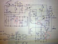
I don't know where would be the end of temperature rising,probably in the smoke.This is my first time to use bulb.Is it OK when she blink when i turn on AC?Is it safe now to remove the bulb?My opinion about temperature rising is transistor.I never mentioned which transistor i planing to use,and You probably think i will use C4706!?My mistake,i use E13009 (700V,12A 24Apeak).Original transistor C4706 is stronger (900V,14A 28Apeak) but i don't see another reson for temp. rising.I don't know does original SMPS have that problem.I know with load there is no heating but i never touching transistor after work without load.(don't wory MicrosiM i turn off Ac before touching case of trans. :) I will replace tommorow transistor with original C4706 to see results.I check everything several times and i am sure everything is OK but i will check again.There is some components with similiar NOT ORIGINAL VALUE!Maybe that is problem!Here on shematic is also few mistakes.With red circle is marked changed values,with yelow circle is mistakes and real values is:both resistor 15R is actualy 51R,capacitor 1uF need revers + and -,zener diode is 6,2V not 12V,small transistor is not PNP it's NPN!!!

FotografijaMARK.JPG

Here what i change:resistor 0,22ohm with 0,18ohm,bleder resistor 680R with 820R and in place 2x75K i put 150K.
So what You thing?
 

MicrosiM

Administrator
Staff member
I don't know how to caracter this results.I connect SMPS to AC with bulb 75W.Everything works and give stable voltage,changing output voltage with resistor also work,but temperature of switch transistor.....See Your self:

I don't know where would be the end of temperature rising,probably in the smoke.This is my first time to use bulb.Is it OK when she blink when i turn on AC?Is it safe now to remove the bulb?My opinion about temperature rising is transistor.I never mentioned which transistor i planing to use,and You probably think i will use C4706!?My mistake,i use E13009 (700V,12A 24Apeak).Original transistor C4706 is stronger (900V,14A 28Apeak) but i don't see another reson for temp. rising.I don't know does original SMPS have that problem.I know with load there is no heating but i never touching transistor after work without load.(don't wory MicrosiM i turn off Ac before touching case of trans. :) I will replace tommorow transistor with original C4706 to see results.I check everything several times and i am sure everything is OK but i will check again.There is some components with similiar NOT ORIGINAL VALUE!Maybe that is problem!Here on shematic is also few mistakes.With red circle is marked changed values,with yelow circle is mistakes and real values is:both resistor 15R is actualy 51R,capacitor 1uF need revers + and -,zener diode is 6,2V not 12V,small transistor is not PNP it's NPN!!!


Here what i change:resistor 0,22ohm with 0,18ohm,bleder resistor 680R with 820R and in place 2x75K i put 150K.
So what You thing?

I am really impressed with the results, very nice try from you to do all this work, since this is really nice try.

Regarding the heat of the transistor, it will be impossible to judge whats going on this way, you MUST use same parts at first place, then when you have a WORKING smps, you can change the way you like.

Also you MUST correct all mistakes into your schematic, and to use same values for all parts, one small value can switch things upside down!

Zener diode value should be the same also

Use a bigger heat sink for that transistor

The tempreture is raising too fast!!, I think its because of the transistor you are using.

There is NO NEED to remove the lamp at this stage, KEEP IT ! until you make sure there is no heat, no problems

the SMPS as it looks is working, only small things to adjust and that's it!

let me know the updates
 

noz-25

LEDadict
I understand.I will try to find correct values for does few parts.It is very good thing for me becouse i have all correct parts on original board,so i will desolder missing parts and put them on my board just to be sure there is no mistakes on my boards.I will use original transistor as well.I will tell You about results!
Thank You very much i really appreciate Your help!Here is NOONE to help me.You and other colleagues on this forum are my only help!Best regards!
Forget to ask,it's obvius that SMPS on first AC turning on "withdraw" lot of current,is there some "soft start circuit " wich i can use here?Thank You!
 
Last edited:

noz-25

LEDadict
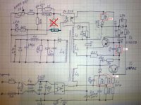
I find lot of mistakes but on shematic!I make mistakes in reading value becouse of fade colour on resistor.But after i correct on mistakes the situation isn't better.Transistor is slow overheating again.That's incredibly becouse mistakes is HUGE!Check this:EDIT SMPS.JPG
You see the bigest mistake,2x47K is correct not 4k7.As You know diferent is betwen red and orange third ring on resistor.It's really luck becouse everything is not burned.Realy stupid mistakes.It's strange how it's work and it's more stranger why not work now!?Maybe small transistor is dead ar some diode.I will check tomorrow,i am tired now.I spend lot of time controling everything.I was planing for today to put original transistor,but when i find these 2x47K resistor as mistake,i was convinced that i solve the problem!If You have some idea-please say!
PS:I notice that bulb blink lot weaker when turn on AC!
PS2:I use NTC becouse it's on original SMPS too.What is about reley who short connect NTC after few second?What is point of that?
 
Last edited:

MicrosiM

Administrator
Staff member
I find lot of mistakes but on shematic!I make mistakes in reading value becouse of fade colour on resistor.But after i correct on mistakes the situation isn't better.Transistor is slow overheating again.That's incredibly becouse mistakes is HUGE!Check this:
You see the bigest mistake,2x47K is correct not 4k7.As You know diferent is betwen red and orange third ring on resistor.It's really luck becouse everything is not burned.Realy stupid mistakes.It's strange how it's work and it's more stranger why not work now!?Maybe small transistor is dead ar some diode.I will check tomorrow,i am tired now.I spend lot of time controling everything.I was planing for today to put original transistor,but when i find these 2x47K resistor as mistake,i was convinced that i solve the problem!If You have some idea-please say!
PS:I notice that bulb blink lot weaker when turn on AC!
PS2:I use NTC becouse it's on original SMPS too.What is about reley who short connect NTC after few second?What is point of that?


Sorry for late replay

You can make a simple circuit later for the soft start.

I am not sure about the problem, it could be anything. did you get it to work by now?
 
Top