diy 500W smps with voltage or current regulation

mojalovaa

New member
Hi folks

I need make smps for some heater 450W (500W) who need work sometimes several hours ( max 16 hours on day with that 450 - 500W ) .
Input voltage 230 V
Output voltage 16 - 24 V (need have voltage regulation for secondary side ) , secondary side not need have rectification .
Output current 20 A
Heating element have 1.3 Ohm resistance (power will change with voltage or current regulation on smps )
Min working time on day 8 hours constant , max working time 16 hours on day .

That can be maybe options like switch transformers for halogen lamp.

Can you give me yours suggestion , or share some circuit diagram and data for diy it ?

I need say that I m make only one smps before 3 years for some LED lamp , and my experience is very small with smps devices .

Thanks all
 

mojalovaa

New member
Hi

Anyone have some suggestion ?

For start will be fine if some one have any circuit diagram who will be start point .
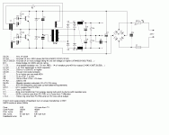
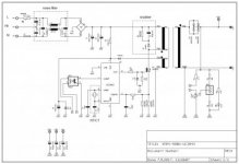
I am found on this forum one circuit diagram who look like nice start options .

Mikro uni.GIF
 
Last edited:

mojalovaa

New member
No one have say something for start help ?

If I wont use top circuit diagram , can I use for start this transistors : http://si.farnell.com/multicomp/bu426a/transistor-npn-to-247/dp/9294112 .
All so for core for transformers , if I wont have 500W power , who dimension for core need be minimum , I m look something like this : http://www.ebay.com/itm/1ste-E4215-...173332?hash=item237e5239d4:g:~8oAAOSwImRYfXNs

Please if some one is make this smps , can share more information with me , like number of turn and similar ?
 

Silvio

Well-known member
You got all the information you need in the schematic and parts list. you also got the number of turns for transformer and also for the output inductors
 

mojalovaa

New member
Thanks Silvio

I see that , but if you are look better that I m write with voltage or current regulation .

On my case I need have options for regulation min and max voltage or current value on secondary wind .

For sample , if max current on my smps is 21 A , then need options that can all so change that current for sample from 10 A min to 21A max , or if is not possible current then voltage for sample form 14 to 24 V .
 

Silvio

Well-known member
You got all the information you need in the schematic and parts list. you also got the number of turns for transformer and also for the output inductors.

With EE 42 core you can get 500 watts all day

The transistors can handle 6 amps continuous so at 155vdc @ 6 amps = 930 watts. they can handle the power easy.

I can help you with the number of turns but the data I have is for PC40 which is equivalent to CF139. It should more or less near.

Regulation of the output voltage however is not available with the circuit shown as this is a self oscillation circuit with no regulation of frequency and neither output voltage.
why don't you look for a circuit with sg3525 or TL494 chip. These will be more complicated but will better in the end for your need of application.
If you want to build an smps you need to have an oscilloscope otherwise you cannot see what is happening in your circuit. You also need an isolation transformer so that you will be safe while tweeking your smps. High voltage is present and is lethal (320vdc)

If you are a beginner like me I would suggest that you start with something simple as a lot of surprises await you until you learn.

One last thing if you want a 24v supply you can always buy a ready made one which can handle the power you need continuous. Most of them will be regulated.

Please read SMPS warnings in the menu bar as smps do not joke when they blow and are dangerous.

Regards,

Silvio
 

mojalovaa

New member
Hi folks

After few day searching who options will be the best for my SMPS with voltage or current regulation I have dilemma .

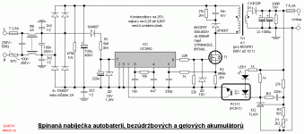
First options that I m think make is with UC3842 , have you experience with that IC , and what is opinions for that options ?
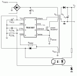
Second options is that I use TEA1507 , that IC have better efficiency but all so not see that people us it allot for diy version , what is opinions for that IC ?

smps-fig3.gifUC3842 flaybuck.png
 

Silvio

Well-known member
Hi folks

After few day searching who options will be the best for my SMPS with voltage or current regulation I have dilemma .

First options that I m think make is with UC3842 , have you experience with that IC , and what is opinions for that options ?
Second options is that I use TEA1507 , that IC have better efficiency but all so not see that people us it allot for diy version , what is opinions for that IC ?

View attachment 6120View attachment 6121

Hello again. I was just wondering if you really need this smps for a heater, well If you come by an old microwave oven that has been discarded you can use the transformer in it and modify it to your needs. You will remove the secondary high voltage winding and re wind it with some insulated wire you will easily get 500 watts out of it. Try to keep things simple. You can make some tappings in the secondary windings to regulate the wattage drawn by the heater.

Coming back to your suggestions regarding the chips you mentioned as you can see they are forward converters and using only one transistor to drive the winding. It is quite some load for a forward converter and if you opt for half bridge topology I guess you will get better results. I will post you a link where you can find a good power supply. It is from 320volt.com You can adopt to use your EE44 transformer instead of the one shown and as for transistors you can use irf 450 or irf 460 these are cheap to buy and can give you a lot of power. You can adopt the circuit with different zener diodes to get a switchable voltage selection hence the heating control.

Link http://320volt.com/en/700w-800w-900w-smps-sg3525-ir2110/

Regards
 

mojalovaa

New member
Hi

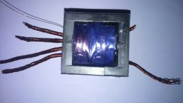
Today I m make one transformers for my SMPS , but I m little confused because have very thick wire on primary and all so on secondary side .
For primary side I m use 6x 0.425 mm2 wire and for secondary side need be used 27 x 0.425 mm2 wire , that is total confuse me because almost is impossible put that on ETD44 core .

I wont use UC3842 for switch FET .

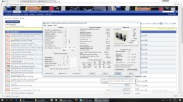
This calculation for transformers is OK ?

DSC_0187.JPG


smps transformers calculation.jpgsmps transformers calculation.jpg
 

Silvio

Well-known member
Hello, arrange your current density in the software to 4A/mm^2 for continuous use, and 6 to 7A/mm^2 for 50% duty cycle without cooling. If you use cooling fan on transformer you can use 7A/mm2 for continuous use.
 

mojalovaa

New member
Hi

Again me and my question :eek:

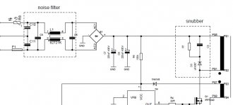
Can some one write me how can calculate noise filter part and snubber part , that is little problems for me on this moment because not have information how do that ?

smps500W.jpg
 

Silvio

Well-known member
Hi

Again me and my question :eek:

Can some one write me how can calculate noise filter part and snubber part , that is little problems for me on this moment because not have information how do that ?

View attachment 6126

Hello again, I am sorry to tell you that I don't have the knowledge to help you here. It seems that this site is DEAD and no one is responding except myself. I have seen your post a few days ago and left it so that maybe someone else may respond but as you see no one did. I was just wondering where the gurus and experts are. I advise you to wait a bit more and if no one crops up with some help you can try your luck somewhere else.

Regards,

Silvio
 

Silvio

Well-known member
Hi Here is a reference book where you may get some information how to calculate the snubber you need. I am providing a link so that you can download it.

https://archive.org/details/
Power_Supply_Cookbook_2nd_Edition_By_Marty_Brown_Newnes_2001_278pp
 

mojalovaa

New member
smps500W-burn part.jpg

Hi

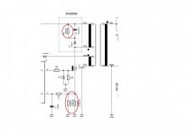
I m start my smps but have allot problems , first is that burn me snubber resistor and FET , then I m add resistor 9R in serial with primary and then little work but not correct .
Frequency is 110 kHz and duty cycle need be 50% if Rsens is correct calculated , that is Vsens/Ipick , 1V/6.6A and that is 0.15R .

Have you idea what is wrong on this part ?
 

mojalovaa

New member
One problem is solved , that is FET burning , problem is be low voltage FET , I m use 500V and 600V FET and that is low how I can see , now for testing use 900V FET .
Like I m write before last day I have few problems with my smps with UC3842 switcher .
First problems is that have voltage on secondary side if not have load , but when add load then voltage from 18.5V drop to 4.6V.
Second problem is when is not connected load to secondary side then burn snubber resistor and capacitor , all so I m try with TVS diode but same problems .

On primary have 29 wind (6 x 0.4 mm2 ) and on secondary have 3 wind (28 x 0.4 mm2).
SMPS is tested on 85 kHz , 92 kHz and 110 kHz and all time is same problems .

Have some one idea what fake me all time ?

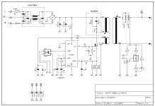
500W smps.jpg
 
Last edited:

Silvio

Well-known member
1) Do you have an oscilloscope?
2) Did you try to put a lamp in series with the input of the power supply so you can prevent any components burning?
3) Did you try to use a lower voltage in the input say 110v instead of 230v
4) The picture of the schematic you uploaded is too small to see post a larger image.
5) Did you look for high voltage spikes and try to adjust snubber to correct it?
6) What current is your smps drawing off load
7) is the wave form changing into something unusual when you load smps?
8) Did you try to remove feedback to see what it does at full duty cycle?

As you can see something is wrong and could be a lot of things. Winding turns in trafo may be too little.
Gap in your trafo may be too large. the more gap the more turns you have to add in primary.
I cannot see schematic do you have details of windings? did you use the same core as in schematic?
0.4 mm ECW can only go up to 100Khz.

I hope that helps

Silvio
 

mojalovaa

New member
signal on pwm.jpg
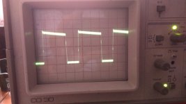
This is pwm signal with out connected FET and primary side off transformers .

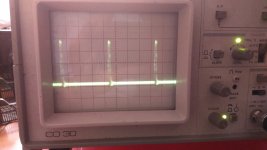
signal without load on secondary side.jpg
PWM signal with out load on secondary side , have only capacitors on secondary .


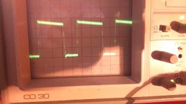
signal with load.jpg
PWM signal with load on secondary side .

500W smps.jpg
 
Last edited:

mojalovaa

New member
proracun transformatora.jpg

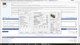
I think that I m found problems , wrong transformer calculation , I m not see that I m use software for forward smps transformers , all so this software have snubber RC calculation and now see that capacitor on snubber need be 50 nF or more and resistor 1.51 k ohm .
All so use only 2 wire for primary coil and 11 for secondary .
Confuse me gape space , I m add 0.2 mm but software say that need be 1.52 mm , that look me very high ?
Now need try wind new transformers and see result , I hope so that will be more better .
 

Attachments

  • proracun transformatora.jpg
    proracun transformatora.jpg
    21 KB · Views: 24
Last edited:

mojalovaa

New member
Hi Silvio

I think that I m found problems , that is snuber , first I m use 1N4007 diode and 5.2 k resistor and all so 3x4.2 nF 1kV capacitor , but then diode is blow , after that I m add 3A 1000V diode and few sec is work fine , after that FET is blow , but before fet is blow I m have on secondary side enough power and 24V on secondary side .
When FET is break out then voltage is go down to 9.6V and then FET is very fast hot .

Will be good if you can look picture for transformer calculation and say me yours opinion , that calculation is ok ?
old transformers calculation.jpg
 

Silvio

Well-known member
Hi I think the calculation is ok but I like to point a few things.
Your current density is too high being 10amps per mm^2 It should be around 6 amps per mm^2 for 50% duty cycle of smps and 4 amps per mm^2 for full duty cycle if you do not use fan cooling. If you use high current density the wire will heat up and also losses will be greater, you will even have more voltage drop due to copper losses.
The snubber diode has to be fast switching. You cannot use 1N4007 but UF4007 or similar

Frequency used do not use too high frequency as switching losses will be too high keep well under 100khz try at 60 or 70Khz. do not forget this is a high power flyback.

The wire that you use to wind transformer has to be according to the frequency used. The higher the frequency the thinner the wire gets. The skin dept that I see on the software is there to guide you so that you don't use wire thicker than the skin dept because it will be useless if you use thicker wire. EXample for 70 Khz you can use wire just under 0,5mm. (0.475mm) This wire has to be used in primary and also in secondary winding. You can use more than one wire to get the needed cross sectional area to handle the current on the particular winding( Primary 5 amps secondary 22 amps)

Try to divide your primary winding in two One half in the bottom then secondary winding then one half of primary on top. If the primary winding will fit in a single layer on the bobbin then make half secondary on the bottom then primary winding then other half of secondary. See what fits best. Make feedback winding on top this carries little current.

Good coupling is needed as the more leakage inductance that you have the more spikes you have on the transistor. A good transformer construction with tight coupling is needed.
Use maylar tape in your transformer normal PVC tape is not good it cannot withstand heat. Use high temperature sleeving at the ends of the winding to insulate well before going out on the transformer pins etc. Be very careful when winding transformer as if primary leaks with secondary it will kill you. I suggest you read the blog post and download the file attached winding small transformers for smps You can also see video on youtube winding small transformers for smps. To see how to wind transformer the correct way.

If you think you have a problem with the software you can ask the author of the program Starichok51 on this website

Hope that helps Silvio
 
Last edited:
Top