diy 500W smps with voltage or current regulation

mojalovaa

New member
Hi

Sorry for late replay .
I m not add current protection because load will be same all time and not have chance that will be change value for this smps .
Today I m replace damage FET and put new , and all so connect LOAD direct to secondary side on smps , after few min work FET is total cold and LOAD is very hot , that look me like good way .
I m see that signal on FET is not total quadratic , maybe because now power come from 310V from capacitor and 10 k resistor for start and after when smps start work come from transformers secondary coil who is wind only for power PWM part ?
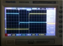
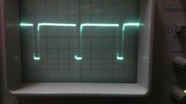
DSC_0060.JPG
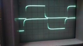
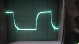
This is signal wave from PWM to FET on Q2
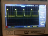
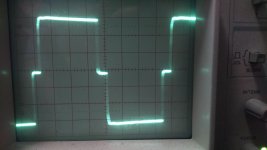
DSC_0062.JPG
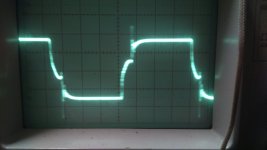
Secondary side voltage wave with connected 15R resistor like LOAD .

Have you idea why have that wave deformation and if you better look you can see some oscillation on dead time , that is wrong snuber or ?
 

Silvio

Well-known member
Have you idea why have that wave deformation and if you better look you can see some oscillation on dead time , that is wrong snuber or ?

If that wave form is coming out of the IR2110 it could be that the auxiliary supply is not strong enough. It looks to me that somehow the voltage seem to sag at the end of the pulse. If the fet is not driven hard enough it will heat up. What series resistor are you using with the fet gates? (IR2110 can give 2A of drive power)

The secondary wave form shows some kind of relation to the switching on the fet gates, a little ringing is also present during switch on and off, however from what I can see its not much. There is always a little ringing when the smps is loaded. The snubber is there to suppress it . It is hard to remove it all. You will check this again when you add feedback as it may need more trimming to the resistor value . You can also add a snubber at the secondary.

regards Silvio
 

mojalovaa

New member
Hi folks , again me and my problems ;ww:
Today I m try run voltage regulation on secondary side and again allot problems .
For voltage regulation I m use TL431 , and plane is have regulation from 15V to 24V .
I m calculate voltage with formula Uout=(1+R1/R2)*Vref , and if you look my circuit diagram then R10 is 43 k , R14 is 8,2k and R15 is 25k (all so try with 50k but same ) and have only 4V difference with max. and min. position for R15 , can say that not work how I m plane , and that is from 15V to 24V .
All so second problems is nex. , plane is that for start SMPS first voltage for run will be come from capacitors (310V ) through R6 , on this test 10 k resistor 3W , and after start SMPS use supplay from transformers on switcher and have rectifier with fast diode , when supply come from resistor 10 k then voltage is 10V , enough for first run and when supply come from transformers then have 18V and then current not need come from 10 k resistor or if will be then will be small , but on real work that not work correct , have you idea how do that ?

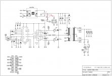
500W-halfbridge-smps-2.jpg
circuit diagram
 

Silvio

Well-known member
It looks that the current is trying to pass through the start up resistor, Put a 11v zener 1watt after the diode so that when the auxiliary takes over it will shut the start up circuit, I cannot see the schematic properly its too small. I also suggest you put 470uf cap on the vcc 18v line. it will give more time for the bulk capacitor to charge up and also it can hold the voltage for a few cycles at start up.
Also take care that when the smps is at minimum duty cycle there is enough voltage at the auxiliary supply otherwise the start up resistor will burn
 

mojalovaa

New member
Hi folks
Today I'm work on smps , first have some changes on circuit diagram and all so I'm replace IRFP450 with IRFP460 and all so make changed on auxiliary supply .
With this change have next problems :
I have some sound on transformer (zzzzzzzzzzzzzzzzzzzzzzzzzzzzzzzzzzzzzzzzzzzzzzzzzzzzzzzzzzzzzzzzzzzzzzzzzzzzzzzzzzzzzzzzzzzz) .
Secondary voltage regulation not work , have only 14V , need be 24 V , all so change output voltage with trimer resistor not work .
Have allot hot on diode and FET heater ( for 3 min have 56 degree celsius )
Can you please help me repair that problems in circuit because need that supply and need run it ?

How I can put here PDF document ?
 

Silvio

Well-known member
You can put your pdf document by going to advance first then you can attach file and upload it

Silvio
 

Silvio

Well-known member
Hello Mojalovaa, I am saying this through my experience on my 1000w smps. I also encountered this problem when trying to regulate the output.
1) You need to put output inductor otherwise wave form on trafo is badly disturbed and trafo starts ticking.
2) You cannot regulate more than 25% less than the maximum output voltage.(19 to 24v) The reason for this is that the bootstrap capacitor does not have enough time to charge up due to the short pulse on PWM and the high side fet cannot switch properly hence the ticking of the trafo.
3) You will always be needing minimum load such as 50 to 100 watts in your case. This will help not to have such a short pulse on the PWM.
4) From what I learnt so far is that to have a better voltage swing on the output a pulse transformer works better. This also has to be well designed and suited for your need. This will give more current on short pulse width.

I hope that helps.

Silvio
 

mojalovaa

New member
This is my circuit diagram and board look .
 

Attachments

  • SG3525-500W-SMPS-V1.2board.pdf
    136.8 KB · Views: 49
  • SG3525-500W-SMPS-V1.2schematic.pdf
    23.7 KB · Views: 40

Silvio

Well-known member
500 watt with voltage or current regulation

1) What current output did you get when smps was not regulated?
2) Was the primary waveform (across primary winding) in good shape when you loaded the un-regulated smps at full load?
3) Is the waveform good shape now (square) when you used the external auxiliary supply. (No like in post #61)?

A little deformation of the waveform is always present when adding feedback. If you start with a bad waveform then it will all loose shape when adding feedback and trafo start saturation

Please write values of resistors around TL431 (R9,10 etc)

Regards, Silvio

Check my feedback loop This works for me

View attachment 1000W SMPS SCHEMATIC V2.pdf
 

mojalovaa

New member
Silvio , how much is power factor on that yours smps?
I think that I'm found problem , that is secondary side voltage regulation , after that I'm make it with zener diode and resistor then work very nice .
For testing now on secondary side have 29V and connected heater 2.1R , then have current 29/2.1= 13.8A , that is total 13.8A x 29V = 400W , and on primary side have 226.7V and 1.9A , that is on primary side 431W , look like 93% effectiveness ?? correct ??
Have very small power factor for that power , that is under 0.59 - 0.61 , but plane is that go up >0.8 , how do that ?

Need make better secondary side regulation , need some sample but quality solution , some one have it ?
 

Silvio

Well-known member
Hi Mojolovaa, good to hear that you are getting results at last, I did not measure power factor on my smps input. Well there tend to be capacitive reactance in the input so you will be needing a series inductor to correct power factor in the input. You can find an input filter from an old computer UPS and feed your mains trough it, The internal inductance will help out with power factor correction. Another option is to fit a ring inductor from an old atx psu around 100 uH in one side of the input AC line.

To check your output power you must measure the input and output voltage at load and also the current at the same time. It is important that you have calibrated meters.

Efficiency = output watts /input watts X 100

93% is a very good result

Secondary regulation My smps did not work properly with zener and resistor only and had the trafo ticking, In my last post I showed you what I did and it works well. The 33v zener is there as the TL431 cannot take higher voltage.

Regards Silvio
 

mojalovaa

New member
Today I'm make few test , one is with output voltage without regulation , then have 34V , then I'm make voltage regulation with zener diode and then have 29V , then I'm connect heater 2.1R , and after few hour work temperature is be only 45 degree with fan , then I'm reduce voltage to 21V and connect 1.1R heater , but now temperature is disaster grow up and then have 82 degree with fan , but if we look have same output power ?
All so RMS current is grow from 1.9A to 2.36A for same power , can you please try explain me ?

Maybe is problems because I m calculate that AC voltage need be 24V but I need DC output voltage 24V , if I will rectify it then voltage grow x1.41 , then I need 18V output on transformers , but then need calculate real current or how much need be for that power , for sample if I need have 24V and 21A output , then need calculate it like 24V or like 24V / 1.41 (then have AC value for voltage , before rectify ?) .
 

Silvio

Well-known member
When you make calculation for output voltage you must always calculate peak first. That peak output voltage will reduce to around 20%, So for example you want 24v dc loaded then you add 20% to that and it will come 24v X 1.2 = 28.8v . so your calculation for peak has to be 29v more or less.

Example For 155vdc input Primary turns = 20 so your volt per turn = 155/20 = 7.75v so for 29v we cannot come exact so we make 4 turns and it comes to 7.75 X 4 =31v

How can we correct it well we try to add 1 turn to primary so we have 155/21 = 7.38v so for 29v we calculate 4 X 7.38 = 29.5v which is quite close now.
B max of the trafo is a little lower but still good

As you can see now that you reduced the output voltage the pulse width is smaller hence also the wave form. The trafo tends to see waveform irregular and does not work well hence the more input current.

Remedy to your existing situation


Try to add more turns to the output inductor so that there will be a bit more voltage drop at the output, this will make the chip to make larger pulse width. and better wave form.

You see what I have been telling you about to start with a good wave form first. This is one reason you are facing problems The other could be the bootstrap capacitor. try change value to lower 2.2 uf and check again. if worse then try 10uf see what happens. You can also try to change gate resistors to 4.7 ohms.
 
Last edited:

mojalovaa

New member
Again smps is dead , temperature with 500W consume go up to 96 degree with fan and then FET is burn , all so IR2110 , jkdgchjdsbvjhvjv ghsvvjgjhcg uzsvv x-( .

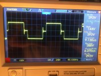
pwm signal in work.jpg
PWM in work look something like this , have some noise , all so wave look me like that is not true square .

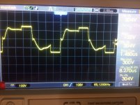
DSC_0087.JPG
This is wave on scope , and like you can see have some noise but I not understand why , look me like that have it from aux supply from EE4215 core ?
 

Silvio

Well-known member
PWM signal from sg should look like this

dead time and frequency.jpg

I can see it that yours has slow rise time

My 1000w smps showing minimum duty cycle monitoring from fet gate

IMG_0653.jpg

minimum duty cycle across primary winding see how it deform

IMG_0647.jpg

look at the heatsink I use for 550 watts continuous

SMPS 550w heatsink.jpg

You can enhance heatsink (make it bigger) or perhaps it can be screwed to the case made of aluminum. Do not let heatsink temp above 70 deg do not forget that junction temperature will be around 15 to 20 deg higher. Try to copy my configuration on compensation at sg3525 and pin 1 and 2. Check wave form again from sg and see if rise time is ok. It looks that noise is getting through the traces feeding the gates. you can put gate to source resistors try 10K first then go down gradually to 1k and see if ringing is suppressed.
 
Last edited:

mojalovaa

New member
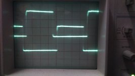
DSC_0089.JPG
PWM signal with out IR2110 (from SG3525)

DSC_0090.JPG
PWM add A+B signal

DSC_0091.JPG
PWM add A+B inverted

Time base is 5u Sec/Cm
For supply I'm use 5VA adapter 18VDC .
 

Silvio

Well-known member
Can I see the pulses from Gate to source after 2110 at low side fet? with no or small load.

Pulses from sg look good and have good rise time. Dead time is also OK do not make below 1uS for the time being.

If you make more tests check voltage at gate and see what is arriving there with volt meter.

If you change frequency to 60 Khz you have to re wind trafo as you need more turns.

You have private message

IMG_0649.jpg
wave form at 400 watt load (1000w smps) notice some spike during switch off of the fet. ( probe across primary)
 

mojalovaa

New member
Now I'm look signal after IR2110 and on top and on down side is not square , look like sine wave , for few minute I will add picture .
 

mojalovaa

New member
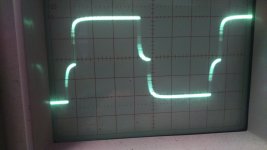
DSC_0092.JPG
DSC_0093.JPG

Wave form after IR2110
 

Attachments

  • SG3525-500W-SMPS-V1.2board.pdf
    136.8 KB · Views: 30
  • SG3525-500W-SMPS-V1.2schematic.pdf
    23.7 KB · Views: 33

Silvio

Well-known member
Which fet is that is it low side or high side?

measure gate voltage during operation with digital voltmeter. I can see that current is dropping during charge up of the gate.

Make sure that the IR2110 is well grounded check for dry joint. I can also see that during switch off current is not pulled all the way and slopes at the end. It seems that it is not switching and sourcing current hard enough and fet is getting in linear region.

It could be that the aux supply not strong enough. Try to help it with aux winding or use stronger supply like bench power supply until you finish tests. The IR2110 can deliver 2 amps of current.
 
Last edited:
Top