diy 500W smps with voltage or current regulation

Silvio

Well-known member
@ res_smps

That is what I also said to myself when designing my 1000 watt smps. I had fast switching diodes capable of 16 amps and they had to handle around 8-10 amps. If it was not for the cpu heatsink I adopted they would have gotten hot for sure. I think switching losses play an important factor. Well he only have to try things out and see what happens. Do not forget that this smps is being designed for continuous rating working around 16 hours a day. In any case he can always change the heatsink to a larger one with more surface area.
 

mojalovaa

New member
res_smps , I'm look little to data for IR2110 and all so see information that boost capacitor is enough 1000 pF (I have 47 uF because I m look other circuit with IR2110 and see that capacitor is under 22-47 uF , but after burn IR2110 then see that is not have time for charge it on 80 kHz frequency .
If I will use 1uF then will be enough time for that frequency , all so for me is strange that for D2 need be fast diode but I will replace it with uF4007 .
Silvio , FET is IRFP450 , that is wrong value on circuit , that is 14A FET 500V , then can have 4.5A constant current , and if have 155V then max. power is 697W .
Diode disipation need be 0.65V x 21A = 13.65W , but if we have that one diode work only 50% of constant power then need be little lower .
Max FET power disipation will be 4.5A * 0.4R (RDS) =V drop DS = 1.8V , then have 4.5A * 1.8W = 8.1W , and if have that work on 50% then have something like 4W heat disipation from one FET .
 

Silvio

Well-known member
mojalovaa; [I said:
Silvio , FET is IRFP450 , that is wrong value on circuit , that is 14A FET 500V , then can have 4.5A constant current , and if have 155V then max. power is 697W .
Diode disipation need be 0.65V x 21A = 13.65W , but if we have that one diode work only 50% of constant power then need be little lower .
Max FET power disipation will be 4.5A * 0.4R (RDS) =V drop DS = 1.8V , then have 4.5A * 1.8W = 8.1W , and if have that work on 50% then have something like 4W heat disipation from one FET .
[/I]

Well the irfp450 fets are good and more than enough. Regarding the heatsink well you have to try things out this being on continuous rating. one must also consider the ambient temperature it will be working in. Based on my experience so far I had to add more metal to the fets and diodes. It could be that I had to compensate for switching losses as well. In your case at 25Khz heat could be more reasonable regarding switching losses

Regarding the bootstrap diode yes as Res suggested it should be a fast switching one. It must recover quickly for the next pulse to charge the capacitor.
I was also reading the application note res sent you and in fact using a bootstrap capacitor cannot get infinite regulation. This explain the fact that using an output inductor will help out things to get a better waveform at the trafo primary. You will also need a minimum load such as 60 watts or so otherwise the output inductance needs to be larger in value and imposes more voltage drop.
 

mojalovaa

New member
Hi folks
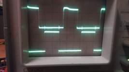
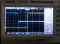
Today I m replace component on PWM module who is last time burn and measure signal on PWM module .
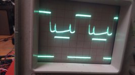
Output signal on SG3525 is fine but output signal after IR2110 i disaster , have some spike on same time when open down FET and for that is burn complete devices I think so ?
DSC_0026.JPG
This is signal on SG3525 output.

DSC_0027.JPG
This is signal on IR2110 output .

Have some one idea what can be wrong , frequency is 80 kHz for FET output ?
 

Silvio

Well-known member
mojalovaa There are two things to try out 1 ) you can make circuit with breadboard for sg and IR2110 and drive 2 leds on output of IR make high side also referenced to ground and drive circuit with power supply 12 volts, you can see wave form if ok, sometimes chips are fake and do not produce good wave form.
2) Remove transformer from PCB and put 60watt bulb instead check wave form and see if it is clean.

What I can see is that when low side fet switch on and off spike is generated on high side gate This will trigger false switching to the fet and reflected to the output, this could be coming from transformer or maybe a trace on the pcb is being coupled to this spike. You can also solder a 100nf ceramic cap directly on the supply pins of IR2110, you can put 18v zener between gate and source to suppress spike, change gate source resistor to 1K ohm instead of 10K the IR2110 has plenty of drive power. Use 10uf bootstrap capacitor it must charge quick at 80Khz

Put snubber on transformer primary. I posted blog post how to calculate values.

I hope that helps
 
Last edited:

mojalovaa

New member
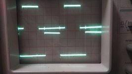
Silvio , I m found problems , I m not make wire from pin 2 to GND , after repair that signal look nice , what you think ?
DSC_0029.JPG
 

Silvio

Well-known member
Yes for me it looks ok. If that signal is with no load you still have to load smps to see what happens to it.

Measure low side fet first Gate to source. After you can measure across primary winding with isolated supply to smps.

measure ringing if any and suppress with snubber across primary.
 
Last edited:

mojalovaa

New member
Hi

Can some one say me how calculate transformers parameters for winding on EI4215 ( 42/21/15 core dimension ZP40 materials ) for half bridge smps?

smps input voltage 205V - 250V AC
Frequency - 50Hz
output voltage - 24V max ( with voltage regulation from 12 to 24V )
Output current max. 21 A
All so interest me how much can expect efficiency and power factor ?
 

Silvio

Well-known member
Hi Mojalovaa I searched for the core material ZP40 but did not find what actually it is. Is it PC40 by any chance? Please give manufacture like TDK, epcos etc. One other thing is that I did not find the core size as EI42 I found EI40. I will be needing the core data to input it to the software otherwise I cannot calculate it for you.

I made an smps with EI40 and I only got a maximum of 450 watts / 70Khz with half bridge. It may be that EI42 may be a bit small for your need.

Regards, Silvio
 

Silvio

Well-known member
Hi Silvio

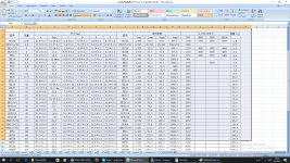
Information for material you can look hear : http://www.lasfcy.com/pages/pro-tx-e.html

On the picture you can see information for core (that is information from producer that core ) .

View attachment 6297

The chart you sent me the core type EI is not mentioned but only EE cores. What type of core have you got is it EE or EI?

You can opt to go to Tahmid's Blog as Res suggested and use the normal formula. Again be careful of the Bmax you choose according to the frequency. If you are using 25Khz and the core you chose is in fact EI42 I think is small for your need. In case you have to rise up the frequency to around 60 or 70Khz but still the core may be a bit small, You need thick copper for the current handling needed and this will make it difficult to fit in a small core.

Regards, Silvio
 

Silvio

Well-known member
Sorry my tape mistake , EE core.
Frequency will be 80 kHz or more if need but max 100 kHz .

I chose the core material N87 which has an AL value a bit less than zp40 as I could not find an exact match. this will be on the safe side not to let the core saturate. I am sending a file worked with Exellent IT 7300 the frequency used is 80Khz and the current density is 6A/mm^2. See what fits best in the trafo bobbin either wires side by side or bundle of wires twisted together. Do not forget margin clearance and use mylar tape in your construction. Use high temperature PT sleeve for primary winding (at the ends of winding)

The file is attached

View attachment Calc for trafo Mojolovaa.pdf
 

mojalovaa

New member
Hi

I m buck to work today , Silvio thanks for calculation .
One question for SG3525 dead time , If I'm look correct on the scope my dead time is 3 uS , and with this calculator that mind more winding on transformers , have some sample for see how calculate dead time on SG3525 ?
My circuit use RT= 2.2 k , CT = 3.3 nF and DT = 100 R .
 

Silvio

Well-known member
Hi

I m buck to work today , Silvio thanks for calculation .
One question for SG3525 dead time , If I'm look correct on the scope my dead time is 3 uS , and with this calculator that mind more winding on transformers , have some sample for see how calculate dead time on SG3525 ?
My circuit use RT= 2.2 k , CT = 3.3 nF and DT = 100 R .

Hi Mojalovaa, I have seen the data sheet of the SG3525 and according to the graph shown I calculated that with a 3.3nf cap you will be needing around 33k series resistor to get 80Khz however you have to experiment a little with the resistor value as it will never be the exact value. You can always put a small preset potentiometer to get to the exact frequency.

Regarding the dead time it all depends if you have a resistor (470K) tied from pin 9 to pin 1 of the sg This will limit your dead time to 1uS. however the discharge resistor will be small around 33 to 100 ohms. If the 470K is eliminated the discharge resistor will be according to the graph shown on the datasheet around 100 ohms or more for 1uS dead time

It will be best to probe with the oscilloscope on both wave forms a put them on each other to calculate the dead time.

This is a Pic of my 1000w smps checking dead time and frequency

dead time and frequency.jpg
 

mojalovaa

New member
Today I'm run my smps and after few second with load is damage , first is burn diode D7 (A1 is short to K ) after that is burn FET , all so short between D and S .
Have you idea why is happen that , because on secondary side after diode voltage is 29V and diode is for 45V , and load is bee 3R and that is 9.6A , but diode is for 40A ?
 

Silvio

Well-known member
Today I'm run my smps and after few second with load is damage , first is burn diode D7 (A1 is short to K ) after that is burn FET , all so short between D and S .
Have you idea why is happen that , because on secondary side after diode voltage is 29V and diode is for 45V , and load is bee 3R and that is 9.6A , but diode is for 40A ?

It looks that your short circuit protection is not set right or it is not working. Did you make a short circuit protection to your PCB? Did you check the wave form at load? Did you work out the snubber value and check it at a partial load to see how it is behaving? You must load gradually and check things out as the more current drawn at the output the more things change regarding stray inductance and also stray coupling to the fet gates. You need to filter out these first otherwise the wave form will be deformed and spikes start emerging everywhere. Load your smps gradually and monitor as you go along. Try to find some heating elements from old heaters and load gradually with them until you go to the final load.

Regarding the output diode it looks like it has exceeded its operating voltage due to spikes on the output.


I hope that helps
 
Top