You are using an out of date browser. It may not display this or other websites correctly.
You should upgrade or use an alternative browser.
You should upgrade or use an alternative browser.
Group Buy 2KW Class-H Amplifier
- Thread starter meanman64
- Start date
Hi Sir information for the 2X18 vac sent to your email.
Thanks mj777 for the email instructions. I am starting to put together the power supplies. What is the 2x18 vac for, also can you send the schematic?
Hi finally got PCB from other member who didnt had time to build this amp.
Now buying components and did read that opto for clip must be of certain manufacturer. Wich one work in this design?
He also sent me all info he got trough email from MJ777 like pics of transistor orientation, BOM, display board schem, psu schem and mods like R43 , R39, Q14, Q16.
But is there any actual schematic with values?
And about QMOS1 and 2 on schematic is FDH3632 but on BOM is IRFP260 wich one is good? Why the change?
Also Q17 is BTL169 on schematic and MCR100-8 on BOM ? Why the change?
I would like to learn how this work so any info i aprecilove.
Thanks
Hi finally got PCB from other member who didnt had time to build this amp.
Now buying components and did read that opto for clip must be of certain manufacturer. Wich one work in this design?
He also sent me all info he got trough email from MJ777 like pics of transistor orientation, BOM, display board schem, psu schem and mods like R43 , R39, Q14, Q16.
But is there any actual schematic with values?
And about QMOS1 and 2 on schematic is FDH3632 but on BOM is IRFP260 wich one is good? Why the change?
Also Q17 is BTL169 on schematic and MCR100-8 on BOM ? Why the change?
I would like to learn how this work so any info i aprecilove.
Thanks
Hello
Answers:-
1- that opto for clip must be of certain manufacturer , YES, I cannot remember witch manufacturer, but that chip used to be WHITE plastic package.
2- There is no actual schematics with values printed on them, Sorry.
3- QMOS1, QMOS2 use IRFP260, they will work just perfect.
4- Q17 is a thyristor, so use any one and do some testings.
FYI, that project came as is, and MJ777 had full success into it, please send him PM, and he will replay.
But if you need anything, also I am here, so dont worry
Regards
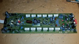
This is what I have so far
I need to put drivers, heatsink, some chips and PSU.
I have a +-55/+-110V psu and +-15V aux supply . What would be a safe procedure to test this amp? What is the steady state current of output transistors ?
I have a big auto transformer so I could start at low voltage for HV and LV like how much?

I need to put drivers, heatsink, some chips and PSU.
I have a +-55/+-110V psu and +-15V aux supply . What would be a safe procedure to test this amp? What is the steady state current of output transistors ?
I have a big auto transformer so I could start at low voltage for HV and LV like how much?

This is what I have so far
I need to put drivers, heatsink, some chips and PSU.
I have a +-55/+-110V psu and +-15V aux supply . What would be a safe procedure to test this amp? What is the steady state current of output transistors ?
I have a big auto transformer so I could start at low voltage for HV and LV like how much?
View attachment 4950
You could use +-30VDC connected to LV, forget about the HV for the testing stage, you should be able to hear clean sound.
Regards
cyriltoledo
New member
hello to the owner of this amp .is this is still available? i love reading this thread..and the amplifier u have presented.. i like it..
cyriltoledo
New member
high quality power amps!!
Yup boards still available
BR,
mj777
Hy, which is the price for one pcb?
