Help on 900 W DC/DC converter

kangoo

New member
Hi All,

I am designing a 100 VDC to 14 volts VDC isolated converter, 70 Amps output.
I will use a full bridge, with one single winding also on secondary side.
Max Duty cycle is 0.45
Core is a TX58 toroid with Al= 2100 nH per turn and Surface= 152 mm²
Bsat=0.15 T
PWM frequency is 40 KHz generated by a good old TL494 (Ct= 1nf Rt= 14K)

I did a preliminary calc to know the primary number of turns:

Nprimary= (Primary voltage * Duty *1000000) /(2* Frequency *Bmax * Surface)
Nprimary= 24.7 turns

Assuming a 1.4 voltage drop on the secondary rectifier, Turns ratio should be close to 100/(14 + 1.4)= 6.5

The Primary current drawn should be close to 70*14/100= 9.8 Amps

Now, the problem come when I calculate the inductance of the primary winding


Lp= Ratio x Ratio x Al
Lp= 24.7 x 24.7 x 2.1= 1281 uH

1281 uH at 40 KHz is quite a big impedance and my SMPS may not work :
So, I did not understood how to deal with this.
I have tried many variations with changing frequency, forcing number of turns, changing also core / material without proper results.

Any help should be really appreciated ;)

Kangoo
 

kangoo

New member
Ooooopps. Made a little mistake.
Should read:

I am designing a 100 VDC to 14 volts VDC isolated converter, 70 Amps output.
I will use a full bridge, with one single winding also on secondary side.
Max Duty cycle is 0.45
Core is a TX58 toroid with Al= 2100 nH per turn and Surface= 152 mm²
Bsat=0.15 T
PWM frequency is 40 KHz generated by a good old TL494 (Ct= 1nf Rt= 14K)

I did a preliminary calc to know the primary number of turns:

Nprimary= (Primary voltage * Duty *1000000) /(2* Frequency *Bmax * Surface)
Nprimary= 24.7 turns

Assuming a 1.4 voltage drop on the secondary rectifier, Turns ratio should be close to 100/(14 + 1.4)= 6.5

The Primary current drawn should be close to 70*14/100= 9.8 Amps

Now, the problem come when I calculate the inductance of the primary winding

Lp= Np turns x Np turns x Al
Lp= 24.7 x 24.7 x 2.1= 1281 uH

1281 uH at 40 KHz is quite a big impedance and my SMPS may not work :
So, I did not understood how to deal with this.
I have tried many variations with changing frequency, forcing number of turns, changing also core / material without proper results.

Any help should be really appreciated

Kangoo
 

wally7856

New member
tx58 toroid $14.66 USD, WOW, they are not giving that one away.

100vdc to 14vdc
tx58 toroid, 152mm^ = Ae = 1.52 cm^
Bsat=0.15 T = 1500G

Ct= 1nF = .001uF
Rt = 14K

F = 1 / Rt x Ct
F = 1 / 14,000 ohms x .000,000,001 uF
F = 71,428 hz

I think you wanted to use 40khz so i will use that number for the transformer calculation.

Pri Turns = 100vdc x 100,000,000 / 4, 40,000 hz, 1500G x 1.52cm^
pri = 27.4 turns


N14 = 27pri x 15vdc / 100vdc = 4.05 turns on secondary, would have to round up to 5 turns.

That is it, you are done. I have never seen anyone worry about the primary inductance if there turns calculation was correct.

My calculations were based on a regulated 100vdc source.
 

kangoo

New member
Thanks Wally.
I Have to check my previous calculation to understand why Rt= 14K and Ct= 1nf has given me 39.29 KHz instead of 71 Khz.
 

wally7856

New member
Oops, i made a small typo showing units. Using uF instead of F, as R is in ohms and C is in Farad’s.

“F = 1 / 14,000 ohms x .000,000,001 uF”

Should have been.

F = 1 / 14,000 ohms x .000,000,001 F
 

kangoo

New member
Thanks Wally.
I Have to check my previous calculation to understand why Rt= 14K and Ct= 1nf has given me 39.29 KHz instead of 71 Khz.
 

kangoo

New member
Hi Guys

I finally made a first prototype of the DC/DC converter, full bridge configuration

Primary= 24 turns
Secondary= 4 turns

Output full bridge rectifier with 8 x 60 A Rms diodes, 2 diodes in parallel per leg.

2.2 n and 10K gives a 50 KHz clock for the TL494 , meaning a 25 KHz square signal measured on the MOSFET gate
when I connect a light load like a 65 W 12 v bulb, circuits works fine, without heating and without noise.
Output voltage is 12 volts, and pwm works fine, giving a constant voltage output when input voltage ranges from 110 DC to 140 volts DC

Then I connected a 12 V 550 Ah battery as output load.
Observed behaviour similar to the one with the 12 V bulb as output load.
System stable, no heat reported on both MOSFETS and output rectifier. Battery being charged at 6 amps current, which is very low for this battery size.
I increased slowly the output voltage up to 14 volts, thus increasing the battery charging current, which is normal when battery as a load.
Input voltage was not adjustable and set at 120 VDC in this case.

BUT, there is a but.
The output current was at 20 amps for about ten seconds, the circuit becomes very noisy, the MOSFETS IXFK140 N30 (140 amps rated, primary side !) got very hot and burnt in a flashlight.

Does anybody here got this kind of sound + light::SD trouble ,?

Andrew
 

kangoo

New member
Hi,

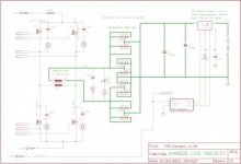
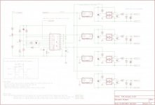
By the way here is the schematics of the prototype.

Note that the "contact" signal starts the converter by feeding a 12 v signal, thus making the PWM outputs to ramp up smoothly.
Note also that the converter need real insulation between 120 VDC input section and 12V output, so current feed back is provided by a (costly) LEM current transducer.

Note also that I have used 3180 optocouplers with a 2.5 amps peak capability to drive a 185 nC gate capacitance at 25 KHz.
These drivers may look a little bit oversized, but they are very rugged.


power.jpgcontrol.jpg

Any help will be appreciated to understand why I burnt the MOSFETS after a few seconds at 20 Amps.

Andrew
 

kangoo

New member
After some investigations, it seems that the core is undersized.
Will come back with a bigger one.
Andrew
 

kangoo

New member
schematic for control + Power section

Should be much easier to read under pdf format ((@
 

Attachments

  • CVS_Kangoo_v1.10.pdf
    57.9 KB · Views: 61

kangoo

New member
Schematic AND Power

Much better with Power section !
 

Attachments

  • CVS_Kangoo_v1.10.pdf
    89.4 KB · Views: 64

kangoo

New member
Hi MicroSim,

The PCB is not in good shape now. Pretty well destroyed. But I restart the design of the toroid core by hand, using mag-inc.com document formula page 4.6 to estimate the power output capability of the core. I found I should have a (Core Area * Window area) greater that 81 cm4 to handle 900 Watts at 50 KHz with B=0.14 . The Toroid I have has a 19.6 cm4 product.

So this is a possible explanation. I did the initial calculation using FERROXCUBE free software and the result was that the TX 58 core was OK.
May be I used this software in the wrong way.

What do you think, Sir ?
 

MicrosiM

Administrator
Staff member
Hi MicroSim,

The PCB is not in good shape now. Pretty well destroyed. But I restart the design of the toroid core by hand, using mag-inc.com document formula page 4.6 to estimate the power output capability of the core. I found I should have a (Core Area * Window area) greater that 81 cm4 to handle 900 Watts at 50 KHz with B=0.14 . The Toroid I have has a 19.6 cm4 product.

So this is a possible explanation. I did the initial calculation using FERROXCUBE free software and the result was that the TX 58 core was OK.
May be I used this software in the wrong way.

What do you think, Sir ?


I really like the design Idea!

But it will be great if you put some pictures, I am not sure about the INPUT voltage of this converter (100V) ?

To help understand the problem, you must show some oscilloscope waves.

What is the color of the core you are using?
 
Top