The inductor is commonly called a feed-choke or series inductor. It has an
inductance large enough in value to maintain a continuous current through the
circuit under all conditions of line and load.
A voltage-fed converter needs that averaging circuit to provide the proper output voltage.
Now is up to you!
Regards,
Marcos Bettecher
inductance large enough in value to maintain a continuous current through the
circuit under all conditions of line and load.
A voltage-fed converter needs that averaging circuit to provide the proper output voltage.
Now is up to you!
Regards,
Marcos Bettecher
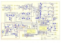
") . i like the protection because if the amp gets over loaded or the amp transistor fails the power supply will switch itself off hopefully
. i like the protection because if the amp gets over loaded or the amp transistor fails the power supply will switch itself off hopefully