You are using an out of date browser. It may not display this or other websites correctly.
You should upgrade or use an alternative browser.
You should upgrade or use an alternative browser.
IR2153 smps with short circuit protection.
- Thread starter norazmi
- Start date
Dzony, ur missing something with smps, take a look back on schematic and pcb at first post, ur almost avoid all bootstrap caps such as 10nf 1kv, and 1nf + 22 ohm at output. its important to have them will keep ur smps working more stable and less heat. Please do it 
regards.
regards.
Azmy, thanks for remanding me, I totaly forgat for snubers... One problem came out... My chasis for amp is Aluminium and 1H high (44mm), I planed to use chasis like big heatsink for IRFP460, if I mount 2 of this SMPS's and 10n 1KV between GND and chasis, can I couse some problem? If that can be good, I can insert separate heastink for each smps without contact with chasis..
Tell me, how can I calculate current transformer, how many turnns on secondary and primary side... I understand how it works: second pin from main transformer (who goes to 1uF and float) is primary of current transformer. That few turns inducate voltage and curent in T106-26 core and on secondary of that core, with diodes 1N4148 we get positiv voltage who is the trigger on MCR100. If current accros primary is low, we dont have enough voltage to trigger MCR100, when current is high, MCR short CT on gnd and IR2153 is "shut down"...
I ask you that because I wanna to learn and use that idea for D class amp like overcurrent protect (secondary can start some elctronic for SD pin)
Thanks again for everything
10nf 1kv it must be close to smps pcb and the other one working like an rf antena to avoid noise coming from swithing device at power mosfet. you can insert separate heatsink no problem with that. For power amp its different application this current sense trafo cannot be applied successful within class D or AB amp, u need to trigger with resistor example 0.5 ohm 5W or any sense resistor to feed the mcr. short circuit protection already include with smps and u need additional amp output short circuit protection which u can use mr bruno design using opto and ne555 to trigger it. That protection can be applied to any amp and any class. That protection is good to be applied into your power amp.
regards.
regards.
hi azmi, it's working now. IN4007 not soldering perfect, sometimes not connected. when i touch it with test pen it's make disconneted rapidly, then the mosfet, ir2153 blown. i replace them, and it's working.
one question, can i remove the bohlam now??
it's normal to hear "click" when start up?
regards.
Glo
one question, can i remove the bohlam now??
it's normal to hear "click" when start up?
regards.
Glo
Attachments
-
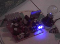 IR2153 first test.JPG17.6 KB · Views: 343
Last edited:
cool, that the thing u need to remember next time. Next time dont make adjustment when u turn on the smps, to adjust or check any component u must turn it off first. Its not like power amp and ur working with high voltage.
yep u can remove the lamp now, click is come from ir2153 and its normal with that. What value of your clamp resistor? And sorry to hear that u blown ur mosfet and ir2153...
regards
and ur working with high voltage.yep u can remove the lamp now, click is come from ir2153 and its normal with that. What value of your clamp resistor? And sorry to hear that u blown ur mosfet and ir2153...
regards
take a clear picture of your smps and sent to my email xwebmaster@gmail.com , take the photo with 3-4 side. its abnormal when fuse blown it should protect main caps and others component. please check your pcb, what core u use? and how do you wind your trafo?
p/s - Dont replace the component and power it up again, your smps run in failure mode and sure it will blown again and again.
p/s - Dont replace the component and power it up again, your smps run in failure mode and sure it will blown again and again.
allright, but not tonight, i will send it tomorrow.
I am using IRF840A, gate resistor 10R. floating caps 2uf/250V.]
trafor winding :
Primary half : 0.3min x 7, 11 turn,
secondary : 0.3 x 10, 5 + 5
aux : 0.3 x 1, 4 turn
half primary, 0.3x7, 11 turn.
my core is ERL35 from Server PS, rated at pure 500WATT.
My the IRF840A can't stand with 10R gate resistor? doi need to reduce of pwm frekuency?
regards
Glo
Last edited: