IR2153 smps with short circuit protection.

MicrosiM

Administrator
Staff member
hi azmi, it's working now. IN4007 not soldering perfect, sometimes not connected. when i touch it with test pen it's make disconneted rapidly, then the mosfet, ir2153 blown. i replace them, and it's working.
one question, can i remove the bohlam now??
it's normal to hear "click" when start up?

regards.
Glo


WHAT???

Playing with SMPS while its connected to the 220VAC line? x-(

that sounds like bad soldering, bad PCB etc..

If you continue this way, you may face your end! :x:

Its normal to get SMPS blown from what you have described! I am sorry for you.

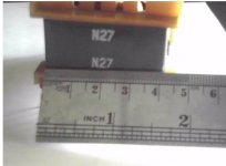
Please, check every thing and show us clear pictures, of PCB , we will try to figure out whats going on.


Regards
 

norazmi

diysmps Senior Member
floating cap just use 1uf 250vdc, its ok with 10r resistor and PLEASE REMOVE AUX 0.3 x 1, 4 turn for testing. and please post and send to my email clear picture of your smps. dont try to power it up again.
 

gloriel

New member
hi all
Microsim, sorry for what i have done, i will not do that again.

Azmi, i am not remove the aux when it blown. i am thinking about the voltage that AUX applied at VCC pin. With Secondary 5 turn, i get 29,6 VDC. With 4 turn of Aux, it's around 24 VDC, limiting current resistor is 33O ohm, will provide about 72ma with 24vdc to Vcc pin. This is to much, and kill the IR2153, make Mosfet short to ground and blown. I compare this with start up current from 47K/5W resistor that only apply 12vdc/ 6.3ma to vcc pin.
The smps working when series with the bulb (40w), as the bulb act as current limiter for the smps.

I have check and check again, main caps not blown, but the plastic was burned when mosfet blown. the trace clean, no short at all. compared with the original schema, the different is only Input Filter.
pls give me some advice.

Regards,
Glo
 

gloriel

New member
i found the ntc is failed. i measure it and get 1.3 ohm, refer to datasheet sck-507 is 5ohm at 25`C. what happen if this ntc defect? can this make the mosfet blown when bulp remove?

regards,

Glo
 

norazmi

diysmps Senior Member
Hi glo, the problem is come from aux supply 24 vdc is too much. originally i state using ei33 and 4 turn, with ei35 is diffrent, thats why i`m asking u before to remove aux winding for testing and i would like suggest u to put voltage regulator for aux supply if u want use aux supply from main trafo. For the main cap 2200 x 2 is ok no problem with that, NTC should be change to 10 ohm and recommended fuse for testing 2 A. This is clearly the problem is come from your aux supply and overload the ir2153 and failed to operation.

regards
 

gloriel

New member
yes i have remove it. primary seems was burn, i tried to measure, give me 99 ohm form CT to first half.
need to winding new trafo. i need to understanding this smps before make 2KW from core below.
 

Attachments

  • EE641.jpg
    EE641.jpg
    98.3 KB · Views: 168
  • EE64.jpg
    EE64.jpg
    158.5 KB · Views: 106

wally7856

New member
yes i have remove it. primary seems was burn, i tried to measure, give me 99 ohm form CT to first half.
need to winding new trafo. i need to understanding this smps before make 2KW from core below.

Gloriel, look at his PDF and give us the dimensions for the transformer you are using and the one you want to use. I will tell you what transformers you have. Need dimensions for A, B, C, D, E, F, H.

Also give us 2 pictures one of each transformer full apart so we can see exactly what type it is. We need to see both half's of the transformer.
 

Attachments

  • Example transformer measurment.pdf
    393.6 KB · Views: 672

norazmi

diysmps Senior Member
hmmmm, too much current through your coil, i cant believe it. Glo as i said, for first try do wind all primary first and all secondary after. mistake on winding technique will burn ur component again....
 

gloriel

New member
hmmmm, too much current through your coil, i cant believe it. Glo as i said, for first try do wind all primary first and all secondary after. mistake on winding technique will burn ur component again....

Hi Azmi, i will winding new trafo, as i have 2 days to make this smps work. do i need make a new pcb?
 

michelle

New member
Hi Stewin
greetings yes the link is working and all files are there i will try to post it here files are big thats why i cant upload it here smps might be helpful
for smps diyers
warm regards
michelle
 

michelle

New member
smps

Hi Stewin
greetings hope this helps all smps diyers
warm regards
michelle
 

Attachments

  • smps 1200.rar
    393.6 KB · Views: 980

michelle

New member
Hi Capsighter
greetings sad i dont have schematic of smps 1200 i found file on net but i am trying to clone 4000 watt smps for my d class amps i am getting
complete kit of smps single sided pcb and will remove smps transformer and get it fabricated in factory and share complete file on diysmps
warm regards
michelle
 

stewin

Member
thanks for the upload andrew. i mean the 1200 smps is it working ,have you managed to try it . and how many turns for each former in the board?
 

michelle

New member
Hi Stewin
greetings well i havent tried it my smps knowledge is nil and to get core is difficult
i will just buy one smps and clone it
warm regards
michelle
 
Top