You are using an out of date browser. It may not display this or other websites correctly.
You should upgrade or use an alternative browser.
You should upgrade or use an alternative browser.
IR2153 smps with short circuit protection.
- Thread starter norazmi
- Start date
pls post pdf file or abigger image components and turns not visiblesomething for smps diyers
warm regards
michelle
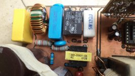
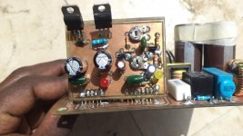
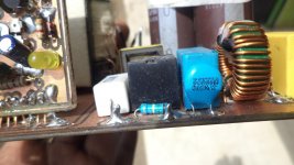
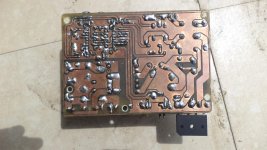
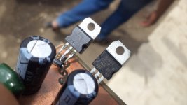
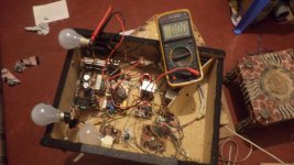
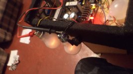
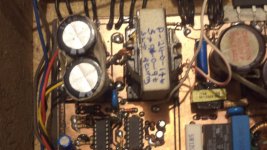
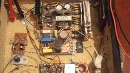
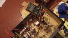
hi guys i thank GOD finally borrowed a camera and was in a hurry . will post clear pictures with details. here is one of the smps
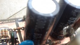
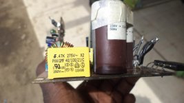
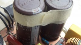
the 3.9k 2wts in pict near the 200v caps i had used them because they were readily available but i later changed them to 2k2 2watts because it works perfectly so i dint use the 3.9k but changed it
")
the 3.9k 2wts in pict near the 200v caps i had used them because they were readily available but i later changed them to 2k2 2watts because it works perfectly so i dint use the 3.9k but changed it
Attachments
-
 DSC01137.jpg182.4 KB · Views: 356
 -
 DSC01124.jpg121 KB · Views: 249
 -
 DSC01125.jpg152.2 KB · Views: 291
 -
 DSC01117.jpg141.8 KB · Views: 281
 -
 DSC01130.jpg114.2 KB · Views: 199
 -
 DSC01118.jpg181.6 KB · Views: 231
 -
 DSC01131.jpg155.9 KB · Views: 173
 -
 DSC01120.jpg176.9 KB · Views: 162
 -
 DSC01135.jpg167.5 KB · Views: 178
 -
 DSC01128.jpg108.3 KB · Views: 135
 -
 DSC01119.jpg181.4 KB · Views: 139
 -
 DSC01123.jpg144.8 KB · Views: 145
 -
 DSC01129.jpg175.2 KB · Views: 127
 -
 DSC01132.jpg208.9 KB · Views: 138
 -
 DSC01121.jpg138 KB · Views: 126
 -
 DSC01122.jpg132.1 KB · Views: 107
 -
 DSC01138.jpg145.4 KB · Views: 124
 -
 DSC01127.jpg117.2 KB · Views: 109
 -
 DSC01134.jpg218.4 KB · Views: 134
 -
 DSC01136.jpg138.7 KB · Views: 133
Last edited:
something for smps diyers
warm regards
michelle
The schematic is to small to read. Please redo with larger picture.
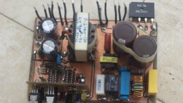
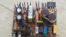
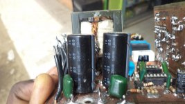
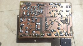
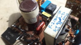
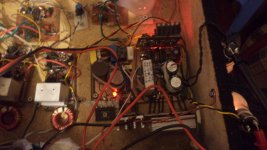
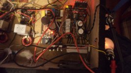
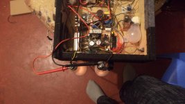
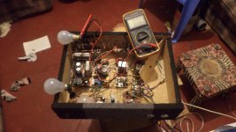
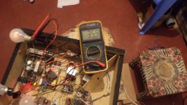
hi guys more photos
i pushed the voltage up to +/-50vlts but i dropped it down to +/-36vlts with (zeener diodes) because i wanted to operate the class d amp i was using with that voltage.
i pushed the voltage up to +/-50vlts but i dropped it down to +/-36vlts with (zeener diodes) because i wanted to operate the class d amp i was using with that voltage.
Attachments
-
 DSC01441.jpg224.7 KB · Views: 94
 -
 DSC01437.jpg205.1 KB · Views: 150
 -
 DSC01460.jpg192.6 KB · Views: 81
 -
 DSC01461.jpg186.8 KB · Views: 76
 -
 DSC01174.jpg185.1 KB · Views: 77
 -
 DSC01454.jpg160.7 KB · Views: 61
 -
 DSC01175.jpg189 KB · Views: 82
 -
 DSC01455.jpg194.1 KB · Views: 58
 -
 DSC01191.jpg119.4 KB · Views: 66
 -
 DSC01181.jpg216.1 KB · Views: 58
 -
 DSC01436.jpg198.9 KB · Views: 107
 -
 DSC01177.jpg177.4 KB · Views: 54
 -
 DSC01444.jpg195.2 KB · Views: 75
 -
 DSC01457.jpg189.4 KB · Views: 56
 -
 DSC01442.jpg205 KB · Views: 63
Last edited:
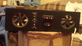
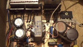
the schema high power with fan control but the input caps that's what to be increased to about 200vlts x 1000uf. I've also corrected the voltage adjustment, this works for me in real life. Sadly, i cant use a potential meter only zeener diodes, but works perfectly and is stable with or without load.
In order for you to change voltage adjust the zeener diodes e.g. if you want +/-40v you use zeeners which will sum up to 80v e.g. 60v and 20v or 70v and 10v etc. I've tried the version with irf740 and it works perfectly, I want to build the one with irfp460 for a bit more power. Here are the schems, I will post the artwork later. The current protection is working perfectly just adjusting the preset potential meter vr1 will help you choose the current you want. For my testing I loaded two 100wts bulbs and the protection responded even to that load.
This cannot be true because there is no output differential inductor used in secondary after diodes to hold energy and perform regulation. You are sending feedback thru opto+zener to error amp of SG3525 for regulating output by varying dutycycle, but where is the output inductor?????????????
This cannot be true because there is no output differential inductor used in secondary after diodes to hold energy and perform regulation. You are sending feedback thru opto+zener to error amp of SG3525 for regulating output by varying dutycycle, but where is the output inductor?????????????
hi kanwar but it is working even now as i am posting this reply. pls have a look at this smps flybuck with half bridge rectification . no output inductors you can google the whole pdf file
Attachments
Last edited:
Flyback operation is totally different than what you are doing as a halfbridge stage driving primary of transformer. In flyback you dont need full bridge rectification because the supply is working in one quadrant only, not like in half bridge which is using 2 quadrants.
Last edited:
rikkitikki
New member
Flyback operation is totally different than what you are doing as a halfbridge stage driving primary of transformer. In flyback you dont need full bridge rectification because the supply is working in one quadrant only, not like in half bridge which is using 2 quadrants.
flyback is not a real transformer, it is two coupled inductors, using the first as a energy storage, then the energy is transfered to the "secondary" by magnetic coupling. It still behaves as an inductor , hence no need for an inductor on the secondary circuit.
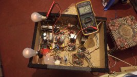
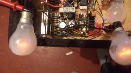
hi all i managed to use this mode of voltage control and it is working i get +/-36vlts dc the smps is cool and working o.k. i have been listening to it all day with class d 200wts amp http://www.diysmps.com/forums/showthread.php?237-Class-D-200-Wrms-with-2-mosfet-cheap/page16
hi Stewin ,
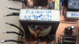
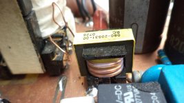
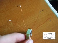
what kind of transformer this smps ? (airgap or ungap )??? if air gap how mm ?
thanks
regards,
Renotrend
valytzu1207
New member
Hello!
I'm building Azmi's SMPS and i have some questions:
1. The 2.7K 1w resistances must be 2.7K or I can put 3.3K or 4.7K for example? (the resistances between plus - gnd and minus - gnd on power output)
2. The value of zenner diode for IR2153 is 13V, can I put a 12V zenner?
3. Instead of MCR100 I put BT151. I think it's ok, right?
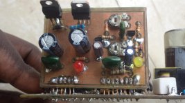
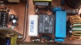
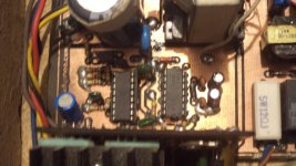
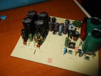
4. On output I put 2 inductors, it is ok? (see photos)
5. How about sense trafo? I make it but I have problems with connection on PCB. How it must be connected on A, B, C points on PCB?
I put all this questions for my safe, i saw that a SMPS is not a joke, it may explode very easy. After this, I want to build the 200w class D amp
This is my first SMPS-)
Thanks,
Vali
I'm building Azmi's SMPS and i have some questions:
1. The 2.7K 1w resistances must be 2.7K or I can put 3.3K or 4.7K for example? (the resistances between plus - gnd and minus - gnd on power output)
2. The value of zenner diode for IR2153 is 13V, can I put a 12V zenner?
3. Instead of MCR100 I put BT151. I think it's ok, right?
4. On output I put 2 inductors, it is ok? (see photos)
5. How about sense trafo? I make it but I have problems with connection on PCB. How it must be connected on A, B, C points on PCB?
I put all this questions for my safe, i saw that a SMPS is not a joke, it may explode very easy. After this, I want to build the 200w class D amp
This is my first SMPS-)
Thanks,
Vali
Attachments
-
 DSCF9911.JPG190 KB · Views: 240
 -
 DSCF9914.JPG212.4 KB · Views: 320
Last edited:
Valy..
1. 2.7k 1W is for +/- 35vdc at output, u can vary the resistance value depends on output voltage, ie: 3.3k 2W good for +/- 50vdc and lower, +/- 60-65 vdc use 4.7k 2w, and etc...
2. the value of zener i use 13V because i dont use external or build on aux supply. 13V will produce about 12.7 vdc after clamping at high supply , ie: use 15K 3W x 2 in series means equal to 30k 6W. When u push smps at peak, with 12V clamping zener the smps might be hickup because of not enough aux supply of ir2153. so to avoid it, u can use more caps bank at main supply, or increase clamping diode to 13V.
3. BT151 it should work, and if incorrect value for the MCR the smps will not turn on. and it will stay at protection mode.
4. Thats ok with DC filter u put and its good. thats not inductor, and its dc filter to avoid noise coming from smps and unwanted noise.
5. refer to back page, i think i already explain how to connect current sense trafo.
hi Stewin ,
what kind of transformer this smps ? (airgap or ungap )??? if air gap how mm ?
thanks
regards,
Renotrend
i used a piece of cd that makes it 1mm thanks.