hi guys . wow finally a smps with working protection all glory goes to the almighty GOD:w):w) it is my dream come true. i have finished the smps . i have not yet found a camera but i will upload photo even if it means using my phone camera . the smps works and the protection works too but the voltage regulation is the one not responding i have cross checked everything .pls check for me if i have to adjust the schema on the voltage regulation side.
You are using an out of date browser. It may not display this or other websites correctly.
You should upgrade or use an alternative browser.
You should upgrade or use an alternative browser.
IR2153 smps with short circuit protection.
- Thread starter norazmi
- Start date
capsighter
New member
@tnx michelle for your reply
@nice project stewin how much power can be produce for your SMPS...
@nice project stewin how much power can be produce for your SMPS...
@tnx michelle for your reply
@nice project stewin how much power can be produce for your SMPS...
thx caps nozarmi said it can do up to 700wts
trying to get correct turns for this smps
warm regards
michelle
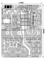
hi andrew try my layout it is smaller it is 98mm x 147mm and if you can replace the irf740 with irfp460 you will get more power but with two pairs only . i,ll try to post one with irfp460 instead of irf740.
stewin smps can go up 800w rms with irf740 with edt49 at 100Khz no problem. you need correct section winding turn ratio for primary and secondary, good caps supply bank at 320 VDC and good diode. More faster diode more efficiency too, and stranded the coil. with IRFP460 can go more than 1Kwrms for sure.
hi all i managed to use this mode of voltage control and it is working i get +/-36vlts dc the smps is cool and working o.k. i have been listening to it all day with class d 200wts amp http://www.diysmps.com/forums/showthread.php?237-Class-D-200-Wrms-with-2-mosfet-cheap/page16
Attachments
Last edited:
 .
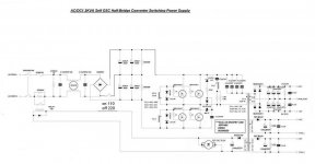
.the schema high power with fan control but the input caps that's what to be increased to about 200vlts x 1000uf. I've also corrected the voltage adjustment, this works for me in real life. Sadly, i cant use a potential meter only zeener diodes, but works perfectly and is stable with or without load.
In order for you to change voltage adjust the zeener diodes e.g. if you want +/-40v you use zeeners which will sum up to 80v e.g. 60v and 20v or 70v and 10v etc. I've tried the version with irf740 and it works perfectly, I want to build the one with irfp460 for a bit more power. Here are the schems, I will post the artwork later. The current protection is working perfectly just adjusting the preset potential meter vr1 will help you choose the current you want. For my testing I loaded two 100wts bulbs and the protection responded even to that load.
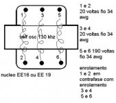
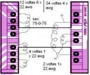
My transormer turns ratio are
>>primary 21 - 0 -13turns,
>> secondary is 9 turns 0-9 turns
>>Aux for fan and IC control 4turns
The other small former
>>Current protect former small from an old ups i see the primary turns are 3turns, the secondary are many, i assume they are 100 turns
It works perfectly with more turns on the primary side, my previous experiments with transformer gate-drive showed that it used less current on the mains if i used more primary turns but you guys can simulate and tell me it i'm wrong
In order for you to change voltage adjust the zeener diodes e.g. if you want +/-40v you use zeeners which will sum up to 80v e.g. 60v and 20v or 70v and 10v etc. I've tried the version with irf740 and it works perfectly, I want to build the one with irfp460 for a bit more power. Here are the schems, I will post the artwork later. The current protection is working perfectly just adjusting the preset potential meter vr1 will help you choose the current you want. For my testing I loaded two 100wts bulbs and the protection responded even to that load.
My transormer turns ratio are
>>primary 21 - 0 -13turns,
>> secondary is 9 turns 0-9 turns
>>Aux for fan and IC control 4turns
The other small former
>>Current protect former small from an old ups i see the primary turns are 3turns, the secondary are many, i assume they are 100 turns
It works perfectly with more turns on the primary side, my previous experiments with transformer gate-drive showed that it used less current on the mains if i used more primary turns but you guys can simulate and tell me it i'm wrong
Attachments
Last edited: