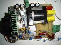
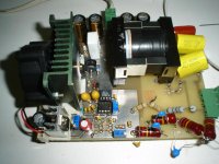
Quasar 1000w smps

tvicol

New member
This is a project we have started more than 1 year ago.
The SMPS was initially designed to power Quasar amplifier, but since then, we ran several group-buys on a Romanian forum and lot of people have buit this SMPS.
Till I redraw schematic, I´ll post here few pictures.


Few youtube pictures made by an diyer.

http://www.youtube.com/watch?v=QwMaHCS1GUY

http://www.youtube.com/watch?v=_NlOd-LE508

http://www.youtube.com/watch?v=xQy9z47J1zs

Regards,
Tibi
 
Last edited:

tvicol

New member
Movies

[video=youtube;QwMaHCS1GUY]http://www.youtube.com/watch?v=QwMaHCS1GUY[/video]

[video=youtube;_NlOd-LE508]http://www.youtube.com/watch?v=_NlOd-LE508[/video]

[video=youtube;xQy9z47J1zs]http://www.youtube.com/watch?v=xQy9z47J1zs[/video]

Regards,
Tibi
 

Sierra

Valve Lover!
Nice Work


Any pricing informations about this SMPS?

Parts List? I need to know if I can get Parts!


Thank You VIECOL
 

josa

New member
Hi
Any reason why you have 2 primaries ?
I would like to make HV smps (need 3.5Kv 1A ) so i would create multiple smps in series, i have E65 cores but am not sure what wire to use for sec / primairies .
For now i am using a bulky 5.5KVA 50 hz transformer to do the job.
Johan
 

tvicol

New member
Hi
Any reason why you have 2 primaries ?
I would like to make HV smps (need 3.5Kv 1A ) so i would create multiple smps in series, i have E65 cores but am not sure what wire to use for sec / primairies .
For now i am using a bulky 5.5KVA 50 hz transformer to do the job.
Johan

There is only one primary, but the winding is splited in two and between primaries was winded the secondary in order to increase efficiency.
Have a look on http://www.vicol-audio.ro/img/smps/Trafo specs_310310.pdf
As for wire we use litzwire 120x0.1

Regards,
Tibi
 

josa

New member
Thanks for the link
Is this 1KW supply mains powered 220V AC in half bridge config ? (whet freq is it running on ?)
If so then i might have to double the number of windings when using the full bridge.
For the secondary if would use just 1 winding and then a bridge rect made with superfast diodes (eg mur4100) is this a good idea, or should i have a center tapped secondaire and use the courrent doubling method with an extra coil ? I am not sure if i can use the current doubling methed when using the bridge.
As for controller i have looked at the ltc1922 lts3722 and i rhink they would be a good choice (ZVS). (played in the past wih lm3524 )
Do you have some other hints for me ? Remember i want to create HV (so i think winding capacitance is important )
I am still wondering how much power the E65 cores can take (3C80) in full bridge config.
Regards Johan
 

josa

New member
Thanks for the info
Did some reading on how to reduce leakage inductance.
I did some testing with half bridge , primary 25Wdg litze, sec 100 wdg , i use a single secondary with a diode bridge (ultrafast mur11000e) 1000v diodes with an extra coil between the bridge + and the output caps. this workt, but as soon i reached 500V, the diodes did blow... , using the scope i saw spikes up to 1KV on the + output of the bridge. I guess i will remove the extra coil and let the leakage inductance do the job.
Could be caused becorse of the lack of a dead time (i drive the 2 fets with the same pulse transformer)
I can't realy find much usefull info here, it seems all to be targeted for class D audio amps. No HV projects here of the order i need.

scale is 100V/div vert.
 

Sierra

Valve Lover!
Thanks for the info
Did some reading on how to reduce leakage inductance.
I did some testing with half bridge , primary 25Wdg litze, sec 100 wdg , i use a single secondary with a diode bridge (ultrafast mur11000e) 1000v diodes with an extra coil between the bridge + and the output caps. this workt, but as soon i reached 500V, the diodes did blow... , using the scope i saw spikes up to 1KV on the + output of the bridge. I guess i will remove the extra coil and let the leakage inductance do the job.
Could be caused becorse of the lack of a dead time (i drive the 2 fets with the same pulse transformer)
I can't realy find much usefull info here, it seems all to be targeted for class D audio amps. No HV projects here of the order i need.

scale is 100V/div vert.


Its better to show schematic you are refering to, with some pictures of your project.
That will help us a lot
 

tvicol

New member
Thanks for the link
Is this 1KW supply mains powered 220V AC in half bridge config ? (whet freq is it running on ?)
If so then i might have to double the number of windings when using the full bridge.
For the secondary if would use just 1 winding and then a bridge rect made with superfast diodes (eg mur4100) is this a good idea, or should i have a center tapped secondaire and use the courrent doubling method with an extra coil ? I am not sure if i can use the current doubling methed when using the bridge.
As for controller i have looked at the ltc1922 lts3722 and i rhink they would be a good choice (ZVS). (played in the past wih lm3524 )
Do you have some other hints for me ? Remember i want to create HV (so i think winding capacitance is important )
I am still wondering how much power the E65 cores can take (3C80) in full bridge config.
Regards Johan

Seems that I have missed some notifications from this forum. :(
The SMPS is able to work from 110V up to 240V.
Frequency is 50KHz.
Output voltages from +/-6V up to +/-150V or 12V to 300V.

regrads,
Tibi
 

MicrosiM

Administrator
Staff member
Thanks for the info
Did some reading on how to reduce leakage inductance.
I did some testing with half bridge , primary 25Wdg litze, sec 100 wdg , i use a single secondary with a diode bridge (ultrafast mur11000e) 1000v diodes with an extra coil between the bridge + and the output caps. this workt, but as soon i reached 500V, the diodes did blow... , using the scope i saw spikes up to 1KV on the + output of the bridge. I guess i will remove the extra coil and let the leakage inductance do the job.
Could be caused becorse of the lack of a dead time (i drive the 2 fets with the same pulse transformer)
I can't realy find much usefull info here, it seems all to be targeted for class D audio amps. No HV projects here of the order i need.

scale is 100V/div vert.


Please show your schematic, We might be able to help
 

tictac

New member
Help Is Always here!

Here you go

PCB + Schematics!

Ready SMPS I have made 1500V output

DSC08179.jpg[DSC08178.jpg
 

Attachments

  • SCH1500.pdf
    17.4 KB · Views: 1,204

CobraNet

Member
1500v

@tictac


Can you tel me transformer turns ratio?


How many volts Max of this power supply?

Thank you...
 

j-paul64

New member
I start with schematics drawing: not checked.
Lower Rds-ON MOSFET for IRFP240?
... Sheet 2 next...
 

Attachments

  • SMPS-SHEET1.pdf
    62 KB · Views: 621

j-paul64

New member
... Sheet 2 and component placement.
Who will check the schematics. I friend of mine, professional power supplies developper will check my job.
in german, Fortsetzung folgt, en francais, à suivre
 

Attachments

  • SMPS-SHEET2-COLOR.pdf
    26.8 KB · Views: 493
  • SMPS-Components.pdf
    65.8 KB · Views: 532
  • SMPS-SHEET1-COLOR.pdf
    62.4 KB · Views: 498

IGBT

Switching Fanatic!
New SMPS

... Sheet 2 and component placement.
Who will check the schematics. I friend of mine, professional power supplies developper will check my job.
in german, Fortsetzung folgt, en francais, à suivre

Is this supposed to be a new SMPS Design ??
 

j-paul64

New member
Not realy!
I will use this design, if checked, for a universal µC battery charger: add CC/CV, balancing and µC-management. I built all my electronics myself, i´d like to know what is in use and the function of the electronic.
Therefore, DIY, but no plagiat, show, learn and built our own equipment.
I don´t like to supply directly the audio amplifier with SMPS, its my opinion, the best sound comes out directly connected batteries. The power supply needs to be very very quiet!
Today, the newest battery technologies allows to charge safety batteries in a few hours...
And there are a lot of audio equipment to be powered: MM/MC-preamplifier, preamplifier, amplifier and I don´t care if tube (my preference) or solid state: all at low output power.
 
Top