UCC3808 12-24V 3A DC-DC problem

gigabyte091

New member
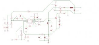
Hi, 2 months ago I started designing my own SMPS based on Texas Instruments UCC3808 Current-mode PWM controller. It's one of the rare PWM controllers (current-mode ones) that have overcurrent protection. Topology i used is Push-Pull with IRFZ44N Power MOSFET's

Schematics is in attachment. It's not copied from internet, it's my own design. If some one want i will give transformer calculation.

My problem is, everything is working, i have 23.9V @ 0A, and voltage stay at that value until i reach 1.5A, then voltage start dropping. Power supply is working at costant power mode. Short circuit current is 280 mA.

As you can see, I added slope compensation becouse duty cycle is above 50% (2×25%).

I wanted to increase current limit, but i cant get out more than 2A, and i tried to modify shunt, then i tried voltage divider to lower the current sense signal (I was carefull not to scramble RC constant on pin 3). Nothing, i just make power supply unstable and noisy.

I tried to modify 20k resistor going from VCC to 2N2905 emiter. Nothing. I tried add aditional shunt resistor. Nothing. I shorted pin 3 to ground, 23.9V even at 5A and no noise at all, MOSFETs are at 28°C

I have no idea what is wrong.
 

Attachments

  • SMPS.jpg
    SMPS.jpg
    13.8 KB · Views: 121
Last edited:

MicrosiM

Administrator
Staff member
I dont think using a resistor directly from the output to the FB pin will make things work.

I recommend that you use TL431 as REF from the output.

I am not sure if the method you are using will work.

I think also you have to use a resistor between pins 1 +2


regards
 

gigabyte091

New member
I will modify feedback with TL431 and optocoupler, i'm waiting for parts to arrive.

So, i should remove capacitors from pins 1 and 2 and leave only resistor.

What do you mean the metod will not work ? Without pin 3, power supply work flawlessly :)

It's my first serious SMPS project.
 

wally7856

New member
I am not the expert here but these are my conclusions.

What i think the problem is with your design is that the emitter of your 2N2905 is not connected to any feedback from the output. The 2N2905 is what controls the current limit.

Looking at this spec sheet, and the schematic on page 7.

http://www.ti.com/lit/ds/symlink/ucc3808-1.pdf

The schematic on page 7 shows some kind of feedback from the opto H11A1 emitter current to the FB pin. It also shows feed back from the collector of the opto to the emitter of the 2N2907. You have no feedback here for current limit.

I do not understand what is going on with the opto emitter feed back in the TI schematic. It is sensing emitter current and feeding it back to the FB pin but i do not know why. But i would say you need to connect your R16, R2, R3 voltage divider to were pin 5 of the opto is on TI schematic. specifically remove the connection R1, C11 to the voltage divider. Then connect the point of pin 5 to the junction R2,R3. You may have to adjust the values of the voltage divider for this new point.

The LED2 and R4 does not belong in the voltage divider. If you want to show you have 24VDC on the output connect it directly to the output.

These modifications seem to me to follow the connection of the opto a little better. But now there will be no feedback to the FB pin, but i do not know if this is bad. Hopefully these suggestions will help other come up with more ideas.

Also from your description, your transformer seems to be working very well. I would like to know how it is made. What core. How many turns and what wire was used, and what order the winding’s were placed.
 

gigabyte091

New member
Hello, i can do better than that, i have pictures of winding process ;)


Primary: 4+4 turns (4×0.4mm wire to reduce skin effect)
Secondary: 16+16 turns (1×0.75mm)

Transformer is from old 300W PC power supply, E-I style, i have no other info about core.
 

gigabyte091

New member
And other photos


First i wound one half of secondary, then isolation, then one half of primary, then another layer of isolation and second half of secondary, then isolation, second half of primary, and two layers of isolation.
 

gigabyte091

New member
yes i did, but i don't know where are the papers because i wound transformer a year ago. My original SMPS was with SG3524
 
Last edited:

gigabyte091

New member
No problem, if I find calculations I will post it.

Back to the subject, does anybody have idea what is wrong ?

I load tested power supply with 3.25A for 13 hours and there was no voltage oscillations, or noise, heatsinks were slightly warm. (Pin 3 shorted to ground)
And that is I think good proof that my design is working propertly.
 
Last edited:

wally7856

New member
The only other thing i can think of for you to check is if the voltage is to high from R11. As the current increases the voltage across R11 increases, bringing pin 3 higher. If you have another resistor the same value as R11, parallel them up and see if that solves the problem.
 

wally7856

New member
If you have an oscilloscope watch the current waveform on R11 and see if it distorts as you increase the current.
 

wally7856

New member
I tried a few different numbers. 40khz looks good to me. With less skin effect.
12vdc, 55,000khz, 1600, Ae 1.18 = 2.89 turns
12vdc, 55,000khz, 1500, Ae 1.18 = 3.08 turns
12vdc, 40,000khz, 1600, Ae 1.18 = 3.97 turns, Best choice.

I think lowering the frequency is a good idea for turns ratio and skin effect. But i do not think it will cure your problem.

Did you try lowering the value of R11. Also if you just disconnect the sense wire to your current shunt at the junction of R12, C9 you should then have full current. If you do not, then you know one more thing it is not.
 

gigabyte091

New member
Hmm, so oscilator frequency should be about 80 kHz (flip flop inside controller devides oscilator frequency by 2). I tried to decrease resistance, it works to some point, but if resistance drop too low, voltage decrease to 12V. Maybe i have problem with wires, too long wire at this frequency become anntena.
 
Last edited:

wally7856

New member
“ if resistance drop too low, voltage decrease to 12V"

Are you saying the output dropped to 12vdc when you lowered the value of R11. I do not see anyway for that to happen. You already said it works OK if you ground pin 3. So if R11 was zero ohms, pin 3 would be at ground.
 
Top