UCC3808 12-24V 3A DC-DC problem

gigabyte091

New member
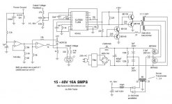
If I short pin 3 directly to ground. But if I short shunt, look better, there is some current flowing trought, R14 and R13
 

wally7856

New member
The frequency you should run the controller at is always confusing. I think if you want it at 40khz at the transformer you set the RC to 40khz also. And i think this is because each output is on for 1/2 the time (per the TI document, page 5). For example 50khz = 20mS, so 50khz / 2 = 10mS. First the waveform goes positive for 10mS and then negative for 10mS, for a total square wave time of 20mS.

You currently have a 1nF (1000pF) and a 26K for your RC, so i think that makes your oscillator run at 55khz and your transformer will run at 55khz.

For 40khz operation looking at the RC chart in TI document you could use either of these.
330pF and 80K
220pF and 135K
Or try there frequency equation to fine tune the resistor value.
 

gigabyte091

New member
Problem solved, i added 1N4007 and 47ohm 2W resistor between VCC of the power supply and VCC of the PWM controller. Power supply is now fully functional. R12 is increased to 3.9k, short circuit current is about 4.6amps, before it was 0.28 amps. Max power i manage to get out is 87 watts, for this shunt configuration, i can increase R12 to about 4.6k, above that, power supply decrease voltage under load to 19V, and start to make continous sound, very quietly. Below that, there is no sound at all, across whole output current range, and voltage is steady, at 3A (rated current) i have about 35-40 mV of voltage drop. That is very good stabilized.
 

wally7856

New member
Good work. Did you move the LED assembly to the output? If you updated the schematic can you re-post with all modifications.
 

MicrosiM

Administrator
Staff member
My UCC3808N chip failed @ 12VDC, and its only working @ 5VDC.

I really don't understand the problem + as mentioned in the datasheet, it should work @ 12V


Can you please tell me the values for the RC network?

Regards
 
Top