1kW smps project (based on MicrosiM design)

try to increase the input voltage to 180VAc

I connect the input through a 600w hair dryer and I have 190V without any load
Then I connect a Heater Element to the out put
The voltage drops to 135 Volts and it drew 2 Amp

Then I remove the dryer and connect the input directly to the 220V ( in my case our outlet voltage is around 240Volts)
The output voltage without any load was 202 Volts
and when I connect the Heater to the output it drops to 185 Volts and it drew 2.8A

I leave the smps with load connected to it for about 30 Sec
The mosfets didn't heat at all but the output diodes get a little hot (I haven't installed the heatsink yet)
 
when I connect the smps to the 220Vac the output voltage without load started to go high (upper than 220V for two rail) and the transformer make a loud noise
but I put a little piece of paper between the sides of core and make a gap
then the voltage stops increasing and the noise from transformer had gone

Is this ok or not? can I create that gap?
 

MicrosiM

Administrator
Staff member
when I connect the smps to the 220Vac the output voltage without load started to go high (upper than 220V for two rail) and the transformer make a loud noise
but I put a little piece of paper between the sides of core and make a gap
then the voltage stops increasing and the noise from transformer had gone

Is this ok or not? can I create that gap?


I think now you have at least a running SMPS, and you have to investigate whats going on.

I think you have some ringing at S+D of your Mosfets, may be at G of Mosfets.

Please show more waves while SMPS @ 240VAC

be careful!!!
 
I think now you have at least a running SMPS, and you have to investigate whats going on.

I think you have some ringing at S+D of your Mosfets, may be at G of Mosfets.

Please show more waves while SMPS @ 240VAC

be careful!!!

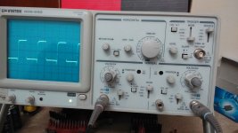
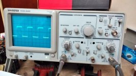
I took picture of the gate of two fets while the output is connected to the load ( heater element : V=181 and I=2.75)
18.jpg
peak of the pulse in the gate of this fet is about 7 Volts

17.jpg
But peak of the pulse in the gate of other fet is about 170 Volts
 
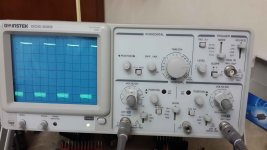
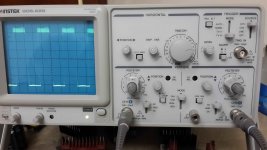
Pictures of oscilloscope connected to the S-D of the mosfets:
20.jpg
D-S of the Q1 >> Probe is connected to "Source" and Com is connected to "Drain"


19.jpg
D-S of the Q2 >> Probe is connected to "Drain" and Com is connected to "Source"


when I reverse Probe and Com of oscilloscope on each mosfet the output voltage drops ( If load connected) and it increase if the load not connected
 

MicrosiM

Administrator
Staff member
Pictures of oscilloscope connected to the S-D of the mosfets:
View attachment 5388
D-S of the Q1 >> Probe is connected to "Source" and Com is connected to "Drain"


View attachment 5389
D-S of the Q2 >> Probe is connected to "Drain" and Com is connected to "Source"


when I reverse Probe and Com of oscilloscope on each mosfet the output voltage drops ( If load connected) and it increase if the load not connected


Try to use some snubbers, start with 100PF and 12R
 
Try to use some snubbers, start with 100PF and 12R

I used above value across D-S of the fets but everything stay exactly the same as before (All Waves above repeated)

I add more load to output and obtained these:

Without load : ~197
With one Heater Element >> 182V >> 2.73A >> ~497 W
With two Heater Element >> 174V >> 4.2A >> ~730 W
With three Heater Element >> 163V >> 6.7A >> ~1100W
With four Heater Element >> 153V >> 8.45 >> ~1300W
are these results bad?

Is there any problems in above Waves taken from the SMPS????


By the way when I attached the third heater element the 5A fuse below
Is this normal and I suppose to increase the fuse amperage? or something is wrong with the circuit?

Once again the capacitor across the input is about 680uf on each rail that should be about 2000uf (according to the schematic) and the capacitors across each rails of the output is 2000uf that should be around 4000uf


Please tell me what do you see that is wrong about this SMPS???
Thank you in advance
 
I manage to add the input capacitors and now each rail has 3*680uf (about 2000uf) and I have this results:

Without loading >> 205V
With one Heater Element >> 191V >> 2.83A >> 540W
With two Heater Element >> 183V >> 5.19A >> 949W
With three Heater Element >> 175V >> 7.3A >> 1277W
With four Heater Element >> 167V >> 9.2A >> 1536W
 
I measured the input ac current of smps and here's the results:
0.15A >>with no load in the output
3.9A >> with 540w drawn from output
6.8A >> with 949w drawn from output
9A >>with 1277w drawn from output
10.9A >>with 1536w drawn from output
 
When i was testing my SMPS me also was doing this error....
So try to use a wattmeter it will calculate the power factor and it will give the real power...
Correct me if i'm wrong... Thanks
 
When i was testing my SMPS me also was doing this error....
So try to use a wattmeter it will calculate the power factor and it will give the real power...
Correct me if i'm wrong... Thanks

I read in "Switchmode Power Supply Handbook 3rd edition" that the power factor for a capacitor input filter is about 0.6

If that's true so the efficiancy will go higher than 95%
 
I want to share my experience with watt meter....
On my SMPS i have 3 capaciters of 680uf.. And the averege power factor is about 0.71
But i will advice you to buy a wattmeter it will cost 20-30 dollars
 
Top