You are using an out of date browser. It may not display this or other websites correctly.
You should upgrade or use an alternative browser.
You should upgrade or use an alternative browser.
1kW smps project (based on MicrosiM design)
- Thread starter ludo3232
- Start date
badboy_6120
Member
Hi
I'm back with some pictures
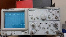
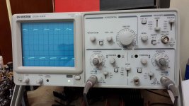
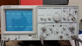
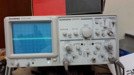
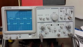
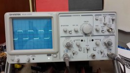
Picture 01 is from Pin 11 of SG3525 (without IR2110 installed)
Picture 02 is from Pin 14 of SG3525 (without IR2110 installed)
Picture 03 is from Pin 11 of SG3525 (with IR2110 installed)
Picture 04 is from Pin 14 of SG3525 (with IR2110 installed)
Picture 05 is from Pin 1 of IR2110
Picture 06 is from Pin 7 of IR2110
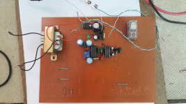
Picture 07 is from the board
All Signals above is according to the ground (pin 12 of SG3525)
badboy_6120
Member
badboy_6120
Member
Is the waves ok?
Can I proceed with the mosfets???
Can I proceed with the mosfets???
badboy_6120
Member
Yes you can solder the mosfets. But show waves at G of mosfets. Not connected 220vac
Hello Microsim
Don't worry
I don't connect the SMPS to 220Vac unless you tell me
I also have a transformer with 40-0-40 volts
also how much power can I get from this power supply??
I want to power my two 500W sub amplifire and two 200W music amplifier
1400W needed at least
I do have ETD59
Do I need to use that for that much power???
Thanks in advance
badboy_6120
Member
Yes you can solder the mosfets. But show waves at G of mosfets. Not connected 220vac
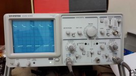
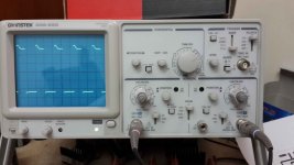
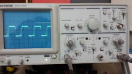
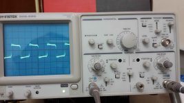
Here is the pictures of oscilloscope connected to Gate of mosfets
Picture 08 and 09 are from the gate of mosfets
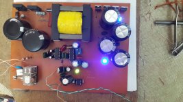
Picture 10 is from the board with mosfets connected
How about it????
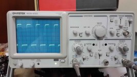
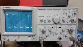
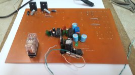
Measurement above is according to the ground
badboy_6120
Member
Dear Microsim
I'm planning to obtain +-80V and +-50V from output
Can you please give me the turns and thickness of primary and secondaries for ETD49 (If 1400W is not possible with this core, please give the information for ETD59)
I have 0.1 mm wire to make Litz wire
Thank you in advance
I'm planning to obtain +-80V and +-50V from output
Can you please give me the turns and thickness of primary and secondaries for ETD49 (If 1400W is not possible with this core, please give the information for ETD59)
I have 0.1 mm wire to make Litz wire
Thank you in advance
Last edited:
badboy_6120
Member
Dear Microsim
I want to do my ETD49 transformer as below:
1/2 primary >> 11 turns
1/2 Secondary >> 13 turns
1/2 Secondary >> 13 turns
1/2 Primary >> 11 turns
My goal : 80-0-80 Volts
I'm gonna use 10*0.1mm for primary and 15*0.1mm for secondary
but the thickness of this much wire seems a little low to me for this much power
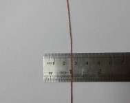
I attach a picture of primary wire that I made
Is this ok?

Dear Microsim
I want to do my ETD49 transformer as below:
1/2 primary >> 11 turns
1/2 Secondary >> 13 turns
1/2 Secondary >> 13 turns
1/2 Primary >> 11 turns
My goal : 80-0-80 Volts
I'm gonna use 10*0.1mm for primary and 15*0.1mm for secondary
but the thickness of this much wire seems a little low to me for this much power
I attach a picture of primary wire that I made
Is this ok?
View attachment 5379
That's thin, I would recommend at least 30x0.1mm for 500w
badboy_6120
Member
That's thin, I would recommend at least 30x0.1mm for 500w
I did this because you told in post 113 yourself
http://www.diysmps.com/forums/showthread.php?79-1kW-smps-project-(based-on-MicrosiM-design)/page12
How about this?
Primary : 60*0.1mm
Secundary : 100*0.1mm
for at least 1000W
I did this because you told in post 113 yourself
http://www.diysmps.com/forums/showthread.php?79-1kW-smps-project-(based-on-MicrosiM-design)/page12
How about this?
Primary : 60*0.1mm
Secundary : 100*0.1mm
for at least 1000W
Correct!! you can use
Primary : 60*0.1mm
Secondary : 100*0.1mm
badboy_6120
Member
Hi microsim
I couldn't find enough 0.1mm wire for that much turns
so I've used 0.25mm wire as below:
primary : 22*0.25mm
secondary : 32*0.25mm
I couldn't find enough 0.1mm wire for that much turns
so I've used 0.25mm wire as below:
primary : 22*0.25mm
secondary : 32*0.25mm
badboy_6120
Member
beside bobbin limitation is there any more limit so I couldn't use more 0.25mm parallel wires for primary and secondary????
badboy_6120
Member
badboy_6120
Member
badboy_6120
Member
Dear microsim
Is everythings ok?
Is everythings ok?
badboy_6120
Member
Did you monitor the heat of the MOsfets?
try to increase the input voltage to 180VAc
With 80vac input there was no heat on mosfets and output diodes
I will increase the input and report back soon

