Dear Microsim any help?
I really cannot tell witch version is the correct one, I advice yout o make a new schematic, then I will review it with you, then you make a protoype. then a PCB
Thats the only way to make a final and succsefull SMPS.
Regards
Dear Microsim any help?
Hi guys, I'm new
I join to ur question badboy, and I have a few, other question:
-Can I do this SMPS without oscilloscope?
-Which PCB and schematic+partlist are the best
-How much $$ parts for this project
Thanks guys, sorry for my eng, Im from pl
I really cannot tell witch version is the correct one, I advice yout o make a new schematic, then I will review it with you, then you make a protoype. then a PCB
Thats the only way to make a final and succsefull SMPS.
Regards
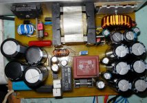
I gathered all the parts of V2.1 of Ludo design
ETD49 (And Even I got ETD59)
wire 0.1 mm for transformer's windings
And other things
you guide so many people in this forum about making a standard PCB for this SMPS but unfortunately they didn't share their PCB with everybody in the end
I want, of course with your help to build the working and standard PCB of this circuit for everyone to use
but I advice you to test the circuit externally if you can
Please protect Tr3View attachment 5365

Hello Microsim
I have all the parts except for MUR120 and MUR1520
But I do have MUR460 and MUR860 and MUR1560
Can I replace them with these????
In Schematic version 2.1 the output diode rectifier are MUR860 but in V3.1 they change to MUR1520 with more capability of current
MUR120 >>>>>replace with >>>>>>>MUR460 ?????
MUR1520 >>>>>> replace with >>>>>MUR1560??? Or should I go with V2.1 Schematic and use MUR860???
Hello
I have small enquiry about Half-bridge smps, I do not feel that I am sure about a few things:
1. Does the half-bridge smps have to allways have output inductors after the rectiflers ?
2. If Yes can some one help me to calculate the choke values ? (Vin = 150V,= V out = 50V, I out = 6A, freq = 70kHz, current ripple 20%)
According to my (I think incorrec calculation) at I outmin = 0.2A the choke must have nearly 1mH ?
Or just putt the value from excellent7300 helper.
Big thanks