1kW smps project (based on MicrosiM design)

Silvio

Well-known member
Hi stewin, I guess you have to adjust the sense resistor (0.1 ohm add a larger value resistor in parallel to make the value to 0.08 ohms for example) make it less and it will need more current to develop the threshold voltage. You can also try to adjust the 2.2K resistor make it larger thus more current before threshold is reached. Hope that helps
 

Silvio

Well-known member
Hi everyone can somebody tell me which is the best capacitor suited for a snubber across the primary winding of a trafo in a half bridge SMPS:-
1) Metalised polypropylene
2) Mylar film
3) Disc ceramic
4) Silvered Mica
5) Transient suppression diode
 
Last edited:

mastanababa

New member
@ Ludo and @MicroSim
Thank you For providing an awesome piece of Work to the community.
I am Building ludo's 3.11Vr Smps and Need to get some modification for the smps
INPUT-110v DC
O/P - 24v Dc @ 22Amps

So My Question is what are the Modifications Needed in the Circuit to achieve the same.
 

MicrosiM

Administrator
Staff member
@ Ludo and @MicroSim
Thank you For providing an awesome piece of Work to the community.
I am Building ludo's 3.11Vr Smps and Need to get some modification for the smps
INPUT-110v DC
O/P - 24v Dc @ 22Amps

So My Question is what are the Modifications Needed in the Circuit to achieve the same.

Enable the voltage doubler for 110V

Change the secondary winding's

Thats all!
 

Silvio

Well-known member
OK, I feel there is serious problem with old design


Please, all use the attached circuit to wire your SG3525, as its 100% tested an correct. and fully working.

Values have to be changed as per your requirements.


Thanks

Hi MicrosiM, I have noticed that there is a change in the PWM (SG3525) drive in version 2. I can see that in the first version R1 and R2 are 10K ohms. These in the second version these two resistors are displayed as R19 and R22 which now are changed to 1K ohms. apart from the other changes regarding the timing resistor and dead time control are now changed to fixed values. I understand that these will bring more stable output frequency and dead time and may not change with vibration as variable resistors may move in time.
As I was testing MY SMPS PWM board I also noticed that the dead time could not go lower than 1.7uS so I changed R6 (version 1 pwm) leading to pin 9 (comp) from 470K to 1M ohm I also had to re-adjust the dead time pot to trim out the dead time to 1uS.

In version 2 modification I also noticed that:-
1) now the compensation (pin 9) is left un-connected
2) The soft start at pin 8 a diode and a series 10K ohm resistor leading to the aux supply voltage was added plus the supply now changed from 15v to 18v
3) pin 1 and pin 2 (sg3525) resistors changed from 10k to 1K

Can you explain what effect on the PWM these changes had? and if it was to make it better in what way did it enhance it?
I am asking these questions because in my PWM I got a spike which I cannot get rid of and it seems to be coming from the PWM when hooked up with the smps

I am posting again the schematics

Regards,

Silvio

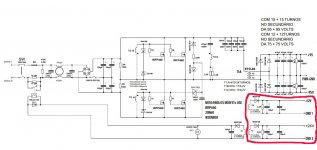
View attachment smps v2.1 sch-1.pdf version 1 schematic


View attachment PWM-Drive2.pdf Modified version 2 schematic
 

vindiesel

New member
hi everybody
i'm totaly new to SMPS but i wound before an ETD39 for my inverter now i have many ETD44 cores and would like to make a design or modify one to make 220v/40-0-40 with 1.5kw or 2kw if could.... is there any way of connecting more than one transformer with ETD44 to achieve this power .... at about may be 100khz

thanks
 

behrad

Member
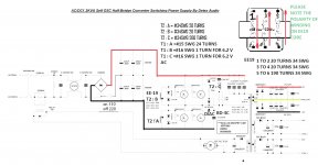
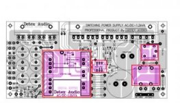
detex 1.2kva smps

hi to all
i want build detex smps
is this good circuit?
how much smps noise?
is it works?
scheme.jpg
jtwqc.jpg

respectfully
 

lucas-nld

New member
hi to all
i want build detex smps
is this good circuit?
how much smps noise?
is it works?
View attachment 6068
View attachment 6069

respectfully
The images you added where much to small, I couldn't make out any of the parts' details. What I could see though seemed like it used 2 pairs of 400V Elco's in series for the input reservoir capacitors, which means they would be rated for twice their individual rated voltages but at half their rated capacitance. You don't need such high voltage ratings for your normal 220VAC offline converter, it would actually be wasteful. Normally pairs of 200V Elco's are used in series, or single 400-450V Elco's are used, but never pairs of 400V Elco's in series.
 

Silvio

Well-known member
Yes you can. Make a double winding with 3 turns I can see that every turn is 6.2v so you will have 18.6v, it will be just right but if the input ac volts is a bit low you may not have enough for regulation. Use a full bridge in the output and use the center tap as common ground for the two regulators.

Regards

Silvio
 

behrad

Member
hi to all
i not found 1n4763(91v zener) in my locale city
can i series 35v+56v zeners and use instead 91v zener??
 

rohin

New member
i am also try to make detex smps for my 250w two channel amp.can any one tell me how to check frequency on smps ?can i check with direct digital meter or special equipment necessary .pre thanks for your suggest.
 

Silvio

Well-known member
Hello Rohin Yes you can check frequency with digital meter but use only ONE probe it will read it just the same.

Hope that helps

Silvio
 

Weller

New member
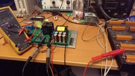
My SMPS.

PFC and half bridge converter.
using variac and isolation transformer.
results when PFC is switched off.

variac voltage, unloaded outputvoltage, loaded outputvoltage, Power (calculated)
100VAC, 64.5VDC, 52VDC 85W
150VAC 93VDC 80VDC 200W
200VAC 121VDC 108VDC 365W
230VAC 138VDC 125VDC 488W

with PFC switched on:

PFC output voltage unloaded: 385VDC
PFC output voltage loaded: 383VDC ripple 5Vpp

227VAC 164VDC 158VDC 780W

IMAG0350.jpg
 
Top