1kW smps project (based on MicrosiM design)

Silvio

Well-known member
Hello MicroSim
Thanks for your Feedback,How exactly I have to engage a voltage doubler since I am Using DC 110v Input.

Since you have a DC input of 110vDC you cannot use the link to engage the voltage doubler. The link was intended to be used on 110vAC. The voltage doubler will not work with DC input.
 

Silvio

Well-known member
So I need to change the turn ratio in the Primary as Well Right.

Well in that case yes if you are still opting to use half bridge topology.
If in your case using 110VDC you can also opt for using push pull topology but this will need to double your primary winding, now having a primary winding with a center tap this being for example 10 turns- center tap -10 turns. However the total cross sectional area of the wire now being half of the original as the current will be divided between the two windings.

New calculations have to be made in a way regarding the fit in the bobbin of your trafo to see how everything will fit with the new topology used. The pcb layout also needs to be changed and traces altered to suit the new topology.

Regarding your turns ratio, well the secondary voltage will reflect with the number of turns used in the primary.

Example: if for example my input dc voltage is 110v and I need 10 turns on each primary then my volts per turn will be 110 / 10 and that will be 11 volts per turn.

Ex. 11v per turn. I need 44volts in the output so 44v divided by 11 = 4 turns.

You can take a look at this video how to wind transformers for smps. The one being shown is for half bridge and has a single primary winding which is done in two sections.

LINK https://www.youtube.com/watch?v=_K3ixhcTYFg&t=956s

I hope that helps.

regards,

Silvio
 

maxente

New member
My SMPS.

PFC and half bridge converter.
using variac and isolation transformer.
results when PFC is switched off.

variac voltage, unloaded outputvoltage, loaded outputvoltage, Power (calculated)
100VAC, 64.5VDC, 52VDC 85W
150VAC 93VDC 80VDC 200W
200VAC 121VDC 108VDC 365W
230VAC 138VDC 125VDC 488W

with PFC switched on:

PFC output voltage unloaded: 385VDC
PFC output voltage loaded: 383VDC ripple 5Vpp

227VAC 164VDC 158VDC 780W

View attachment 6107

@Weller can you post the schematic of your PFC ?
 

Weller

New member
I used UCC28180.

My schematics are quite the same as in the datasheet.

The trick is how to hold the converter in continues conduction mode over a wide power and input voltage range.
 

2ner

New member
My SMPS.

PFC and half bridge converter.
using variac and isolation transformer.
results when PFC is switched off.

variac voltage, unloaded outputvoltage, loaded outputvoltage, Power (calculated)
100VAC, 64.5VDC, 52VDC 85W
150VAC 93VDC 80VDC 200W
200VAC 121VDC 108VDC 365W
230VAC 138VDC 125VDC 488W

with PFC switched on:

PFC output voltage unloaded: 385VDC
PFC output voltage loaded: 383VDC ripple 5Vpp

227VAC 164VDC 158VDC 780W

View attachment 6107

looks good, but your magnetics are huge for such small power, that should be multi kw supply or very low switching freq.
 
Hello guys
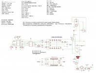
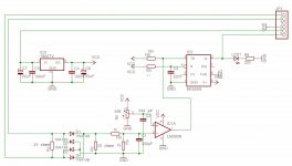
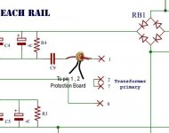
Here's Schematic of ludo SMPS with all modifications
000000000000000000000.jpg 5.jpg

I have a problem with protection board
No matter what I set the value of trimmer on protection board I couldn't trigger the protection unit with connections of any load (Even 1500W)
but at start up I can easily set the kick in point ( like it could start whit loads lower that 700W but not more than that)
So what seems to be the problem here ??? I hadn't this problem before
Any help would be appreciated
 

MicrosiM

Administrator
Staff member
Hello guys
Here's Schematic of ludo SMPS with all modifications
View attachment 6383 View attachment 6384

I have a problem with protection board
No matter what I set the value of trimmer on protection board I couldn't trigger the protection unit with connections of any load (Even 1500W)
but at start up I can easily set the kick in point ( like it could start whit loads lower that 700W but not more than that)
So what seems to be the problem here ??? I hadn't this problem before
Any help would be appreciated


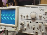
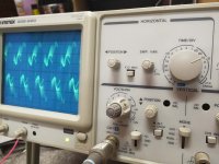
Load the SMPS with 500W and show me the wave across the CS transformer.
 

Silvio

Well-known member
@Badboy_6120
It may be that you don't have enough coupling with the one turn loop around the current trafo. I suggest that you tread your wire from the center of the core and cross them on the bottom by putting the end that goes to the front on the back hole of the pcb and the back end to the front hole on the pcb thus creating a 1.5 trun coupling loop.
I tried this circuit and worked for me. The only problem I had was it was too sensitive and had to dump a little the rise time on the current trafo by adding a small capacitor across the secondary of the current trafo
If you want to make it more sensitive you can also try to make a higher value load resistor like 15 or 22 ohms instead of 10 ohms.

I hope that helps
 
I didn't have a 500w load exactly but I did 2 test for you:
one with 370W :

370.jpg

and another one with 640W :

640.jpg

Volt division is on 1 and the probe attenuation is on 1x
 
Last edited:
I will try that and let you know the result

I did use higher resisters and it did raise the sensitivity, but only on smps start up and not while it's running
before that I said the protection board was working just fine I was using 10 ohms resister too, so I don't think that's the problem
 

Silvio

Well-known member
@Badboy_6120

Take a look at the picture in the bottom of this blog post. It shows how to couple with the 1.5 turn coupling loop.

http://www.diysmps.com/forums/entry.php?149-Current-transformer-calculation.

You can make a test with your protection board by using a variable power supply and check what dc voltage is needed to trigger the LM393 and 555 output. It would be in the region of 1v or so. You can tie a small pot or preset across a 2 or 3v supply and take the voltage to the protection board via the wiper of the preset. There you will know what is the closing voltage. Now with comparison while the smps is working you can measure the output across the 10 ohms resistor and see what are you getting there. IF the output is far lower than what you expect it means either you need more turns on the current trafo secondary or it may be the case that the current trafo core you are using is not suitable for the job.

At the time I made my smps I did not have this issue but on the contrary it was too sensitive. I loaded the current trafo in two sections hence I am using 2 resistors of 22 ohms each in parallel. one is placed directly across the the secondary winding and the other is after the diode bridge shorting the output. I also noticed that these resistors get rather hot on high load and that was the reason I used 2 metal film resistors rated at 3watts each. Please check your ICs and see that they are good ones not fakes.

Regards Silvio
 
I reduced CT turns to 15 and removed R1 and now everything is ok
SMPS will start with less than 400w load connected and after that it will trigger if the load goes above 1500w
This is a good thing for me because the subwoofer protection that I'm using will not connect the subwoofer to amplifier output in less than 2 seconds.

I just want to know that is reducing CT turns and removing R1(I also put a 220 ohms resistor here but the result is the same as none) gonna effect the function of protection board in long term usage?
 
Last edited:
Top